Simulation
Cardiac Ultrasound
The use of simulators for training in echocardiography is
not novel. The use of simulator for measuring technical (psychomotor) skill in
surgery is also not novel.
The feature that we introduce is using simulation to
measure competence in the technical skill of image acquisition. Current
practice is for faculty to visually gauge trainee competence in ultrasound. The
simulator now permits quantitative and objective measurement of technical skill
in acquiring images. Cognitive skill in making the correct diagnosis
from images can also be evaluated.
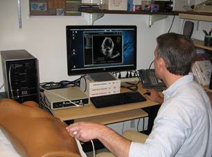 Left:
The simulator comprises a mannequin, a mock transducer, and a computer. In this
first version, the transducer position and orientation on the mannequin are
tracked using a magnetic field system.
Left:
The simulator comprises a mannequin, a mock transducer, and a computer. In this
first version, the transducer position and orientation on the mannequin are
tracked using a magnetic field system.
As a user “scans” the mannequin, a three-dimensional (3D)
ultrasound data set is cut into a two-dimensional (2D) ultrasound cine loop at
the plane that corresponds to the position of the transducer on the mannequin.
Each 3D data set was previously recorded from a patient and registered to the
mannequin. The 2D image is displayed on the computer monitor. For training, a
3D reconstruction of the patient’s heart chambers is also displayed to help
users understand the anatomy they are seeing in their 2D images. The 3D display
also shows where the transducer is scanning in the heart.
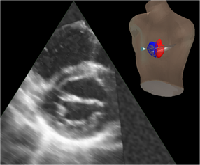 Left:
Example of 2D ultrasound image cut from a 3D data set, with inset showing the
mannequin, 3D heart reconstruction, and pointer to the view plane. In the
reconstruction, the left atrium and left ventricle are in red and the right
atrium and right ventricle are in blue. The pointer leads the eye to the view
plane, which contains the 2D image.
Left:
Example of 2D ultrasound image cut from a 3D data set, with inset showing the
mannequin, 3D heart reconstruction, and pointer to the view plane. In the
reconstruction, the left atrium and left ventricle are in red and the right
atrium and right ventricle are in blue. The pointer leads the eye to the view
plane, which contains the 2D image.
The competence assessment measures the positional
accuracy of each view plane in terms of location and angle. The correct view
plane is defined using anatomic landmarks from the 3D reconstructions. For
example, the 4-chamber view is the plane that contains the centroid of the
mitral annulus, the centroid of the tricuspid annulus, and the apex of the left
ventricle. Error in location is measured as distance in the center of the view
between the acquired view and the correct view.
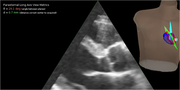 Left:
In this example, the parasternal long axis view that was acquired (blue plane)
differs from the correct, anatomically defined view (green plane) by only 0.7
mm in location but the angular error is 29.1°.
Left:
In this example, the parasternal long axis view that was acquired (blue plane)
differs from the correct, anatomically defined view (green plane) by only 0.7
mm in location but the angular error is 29.1°.
Image interpretation is performed after the user has
finished imaging the heart, as is the clinical routine. The images are
displayed for review, and questions on findings and diagnoses are presented.
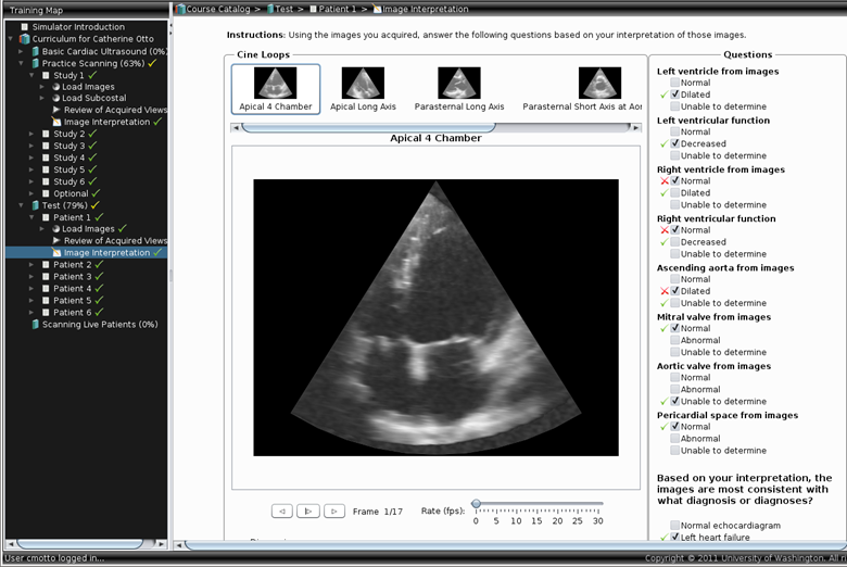
Left: User interface for image interpretation.
This simulator was developed with funding from:
The Edward J. Stemmler, MD,
Medical Education Research Fund of the National Board of Medical Examiners; the Coulter Foundation for Translational Research; and the John L. Locke, Jr. Charitable Trust
Orthopedic Surgery
The objective of this project was to develop a method to
measure procedural competence in an objective and quantitative manner. The
procedure targeted was osteotomy for repair of femoral malunion, a condition in
which the femur failed to heal properly following a fracture and the patient is
left with a deformed and dysfunctional leg.
The training interface presents a clinical case to the
user along with antero-posterior (AP) and lateral
x-rays of the leg. The first task is to measure the deformity in terms of the
angular deviation from the contralateral leg, which is assumed to be normal.
Left: User interface for calculating angle of deformity.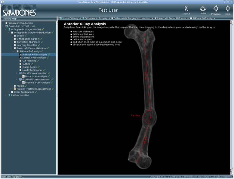
The user then performs the osteotomy on a simulated bone
by sawing out a wedge. The plane of the cut is measured from a
three-dimensional (3D) reconstruction of the bone generated by imaging laser
lines projected onto the cut bone while rotating the bone.
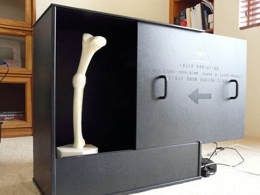 Left:
Imaging apparatus. The bone is secured in a vertical position on a rotating
stage. The laser and camera are behind the door.
Left:
Imaging apparatus. The bone is secured in a vertical position on a rotating
stage. The laser and camera are behind the door.

Left: Surface mesh of cut bone with plane of cut
identified at top (gray plane). The anatomically defined correct cut is also
shown (red plane). Error is measured in terms of the difference between the
planes in angle and position.
This simulator was developed with funding from Pacific Research Labs