Spherical Decomposition Extension
ExtensionThis document offers an overview of angular domain Ambisonic soundfield decomposition and spherical domain recomposition.
Introduction
Before continuing, you'll find it helpful to review:
- Domain formats
- Spatial domains
- Spherical decompostion
- Ambisonic Soundfield Model
- Near-Field Effect (NFE)
A mature Ambisonic workflow requires tools to support freely moving between the spherical and angular domains. In particular, certain tasks are more readily performed in one domain over another. For instance, if we'd like to process various elements of a soundfield separately, we need a way to separate a soundfield into equally sampled parts.
One task could be to apply different frequency domain filtering to different parts of the soundfield. Another task could be to apply dynamic range reduction, which varies spatially. Yet another could be to add different time domain effects (think reverb) across the soundfield.
In the ideal case, we'd like to have control of both angular and radial sampling for decomposition and recomposition.
Here we consider the operative tools and techniques.
FOA vs HOA
The main differences between the ATK's two toolsets may be summarized as:
| angular domain | beams | reference radius | basic wave | decoder | |
| FOA | tetrahedron | 4 | infinity | planewave | FoaDecoderMatrix: *newBtoA |
| HOA | t-design | +ASSR | 1.5 meters | spherical wave | HoaMatrixDecoder: *newSphericalDesign |
- ASSR
- angular spatial sampling rate
FOA
The ATK's FOA toolset includes the facility to between the spherical and angular domain.
With the FOA implementation, we can consider:
- beam shape
- look direction
- beamforming radius
FoaDecoderMatrix: *newBtoA and FoaEncoderMatrix: *newAtoB are used to manage the first two topics, while FoaNFC and FoaProximity address radial decoding and (re-)encoding.
Choosing the beamforming radius allows us to choose what kind of waves make up our angular decomposition. E.g., near-field, or far-field spherical waves. We'll review each of these topics below.
________________
To begin with, try:
A matched decoder and encoder pair will return an identity matrix. Given no signal processing in between, reencoding returns the original soundfield:
Angular sampling (FOA)
For FOA, the angular sampling returns the minimum number of beams optimized for preserving total soundfield energy.
Let's view with PointView:
Go ahead and touch the GUI with your mouse or pointer to re-orient the display.
This should appear familiar: ABCs of the ATK: Tetrahedral Recording
Beam shapes (FOA)
For FOA, the ATK's toolset includes four beam shapes:
- strict soundfield
- strict soundfield (N2D)1
- energy optimised
- controlled opposites
You can review this table to see how these are assigned via the weight keyword argument. The default is strict soundfield.
These are the windows into the soundfield. For decomposition and recomposition, strict soundfield will be our first choice. Without radial filtering, this corresponds to decomposing (or recomposing) a soundfield as a collection of four planewaves.
In principle, we should choose matching beam shapes on decoding and reencoding.
Orientation (FOA)
We have eight orientation options to choose from, accessed via the orientation keyword argument. Let's try \fbd:
And view:
You'll see we've oriented the tetrahedron so that the first beam looks directly at [ 0, 0 ].
Planewaves (FOA)
The ATK's FOA reference radius is infinity:
As a result, in FOA a basic wave is a planewave. Therefore a decomposition with FoaDecoderMatrix: *newBtoA, a real matrix operation, will return a planewave decomposition.
Here's an illustration of the network:
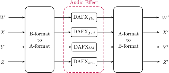
DAFX in FOA
Here's some code:
Spherical waves (FOA)
By employing the procedure illustrated here, we can decompose the soundfield into spherical waves, rather than planewaves. We'll specify a look radius, which is the radius at which the soundfield will be decomposed and resynthesized:
What we're really doing is converting the spherical waves at ~radius to basic waves (no imaginary encoding coefficients) by using FoaNFC.
The soundfield is then being decomposed.
After recomposition, the imaginary components are resynthesized via FoaProximity.
We can think of this as:
- flattening the curved spherical waves
- decomposing to a collection of beams (to the angular domain)
- (doing some processing)
- re-composing a colleciton of beams (from the angular domain)
- recurving the flattened waves
HOA
The ATK's HOA toolset substantially expands the choices we can make when moving between the spherical and angular domain.
We have a number of factors to consider:
- number of beams (angular windows)
- beam shape
- look direction
- beamforming radius
The SphericalDesign class is behind much of this added flexibility, and either directly, or partly manages the first three factors.
Choosing the beamforming radius allows us to choose what kind of waves make up our angular decomposition. E.g., near-field, or far-field spherical waves. We'll review each of these topics below.
Angular sampling (HOA)
While there is a minimum angular spatial sampling rate that must be met for successful decomposition and recomposition, we may easily choose a higher number of beams to form:
We can see that we have a large number of choices for third order, optimized for preserving total energy. The minimum number of beams we can choose is 24.
Conveniently, TDesign: *newHoa will return a minimum sized spherical design for a given optimization:
If we choose fifth order, we see that the minimum number of spatial windows required is 60. If we want to ensure that energy is smoothed evenely across the sphere, the minimum is 70.
How should we think about this?
As the order increases, the window size decreases. To cover the sphere, we need more windows:
Beam shape (HOA)
Traditionally, Ambisonics offers three standard beam shapes:
- strict soundfield
- energy optimised
- controlled opposites
These beams are the spatial basis functions we're using to represent the soundfield in the angular domain. We can also think of these are spatial windows.2
In most cases, strict soundfield will usually be the appropriate choice, and for NFC-HOA corresponds to decomposing (or recomposing) a soundfield as a collection of spherical waves.
If we wish to reconstruct (or re-encode) a soundfield in the spherical domain after decomposition (decode) to the angular domain, the beam shapes of the decoder and (re-)encoder should match.
________________
One interesting possibility where beam shapes are intentionally not matched is the use of a DSP process to synthesize spatial artifacts as a kind of lower to higher order "upsampling".
These two beams have a similar size:
A use pattern could be:
Processing in A-format (the angular domain) must involve differences in amplitude and/or phase between the individual A-format channels to synthesize any additional spatial information.
Think of this as "roughing up" some feature of the soundfield in order to create more detail.
Orientation (HOA)
We may wish to alter the orientation of spherical design so that an encoded sound of interest appears at the look direction of a specific window.
Let's make a minimum sized t-design for third order:
We can request the design look directions:
And:
If our sound of interest is located on the x-axis, directly in front, we can see that on angular decomposition, this sound would be distributed among four beams.
We can re-orient the t-design so that a single beam is directed at the position of interest:
Have a look:
For this design, the new orientation no longer appears to be symmetric across the axes. If that's an issue, we can easily explore other available designs.
Spherical waves (HOA)
The ATK's HOA reference radius is 1.5 meters:
If we use the strict soundfield beam shape to decode (deconstruct!) a soundfield to the angular domain, we're decomposing the soundfield to a collection of spherical waves located 1.5 meters from the origin.
Here's an example illustrating decomposition and recomposition at the reference radius:
If we'd like to choose another radius, we need to move the reference radius, i.e., move where the basic wave is encoded in the soundfield. To do so, we'll use a pair of HoaNFCtrl UGens. The first moves the basic wave (real coefficient encoding) to the source radius. The second returns the basic encoding to the original source radius.
Here's an example:
Planewaves (HOA)
While in theory we can decompose NFC-HOA soundfield as a collection of planewaves, due to numerical issues, doing so isn't always practical. The usual advice is to choose a radius that is planewave-ish. For most sounds, a radius greater than 5 meters will likely be fine.
________________
For completeness, let's consider the problem in more detail.
The difficulty to be overcome actually has to do with resetting the reference radius to infinity before decoding to the angular domain. HoaNFProx does this translation. The issue arises in that the filtering for higher degrees involves integration, and is therefore numerically unstable.
One way to attempt to mitigate is to prefilter the soundfield with higher order highpass filters. In practice, with real-world networks, doing so asking for trouble.
But... since we can... let's ask:
BIGLY WARNING: Really! Don't even think about trying this in my studio!!!
BIGGEST WARNING: You fool! Are you still considering going there?!?
link::Guides/HOA-Spherical::