Van Dyck Group — Penning Trap Mass Spectrometry
Penning Trap Mass Spectrometry Research
Overview and History
We conduct ultra-high precision mass measurements on trapped single ions using Penning traps. This work was started at the University of Washington by Hans Dehmelt in the 1960's and has continued to flourish, yielding a Nobel prize for Prof. Dehmelt in 1989. Prof. Van Dyck joined the group in 1971 as a post-doc, working on the g-2 experiment for electrons, which measured the magnetic moment for the electron to ultra-high precision. He started the ion mass spectrometry experiments here at UW in 1976, and since that time our experiments have yielded accuracies at or near the top of the field (current resolution for our spectrometer is about 1 part in 1011). Our mass measurements have seen a variety of applications, and our current work on Helium-3 and Tritium will be used in the first direct neutrino mass measurement by KATRIN.
How a Penning trap traps
A Penning trap is a three electrode device (in its simplest
form) which traps charged particles with electric and magnetic
fields. The constant magnetic field traps the particle in the
radial direction while the quadropole electric field traps the
particle in the vertical or axial direction. This induces three
modes of motion - the axial (due to the applied electric field),
the radial cyclotron (due to the magnetic field, and the radial
magnetron (due to the presence of crossed E and B fields). The
three electrodes consist of endcaps
at either end and a
ring
between the endcaps.
How we look
at the trapped particle
The trapped particle undergoes simple harmonic motion in the axial direction. This up and down motion by a charged ion induces a tiny AC image current in the endcap electrode. The current is then sent through a highly tuned LC filter, which transforms the tiny signal into an AC voltage. The frequency of this AC voltage is exactly the frequency of the axial mode. This is how information is transmitted from the particle to us. The voltage is then amplified by a GaAs FET amplifier and sent to the detection electronics.
How we measure masses
The three modes of motion are given by (typical values taken from Deuterium appear in parentheses):
Axial:
Cyclotron:
Magnetron:


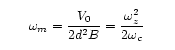
One will notice that both the axial and cyclotron frequencies depend on mass. It might be tempting to immediately take the mass from the axial, since that is the mode that we immediately see in our detector. However, variations in both the trap constant d and the voltage V limit the accuracy. The cyclotron mode is a good one, but direct observation is impractical because its linewidth is simply to narrow to be properly resolved by our detector. We actually lock the axial frequency with a feedback loop (so it stays constant despite the variations), and then couple the cyclotron mode to the axial mode by putting slight imperfections into either the magnetic field or the electric field. These imperfections then pick up terms in the axial and radial motion, effectively coupling the two modes. The cyclotron motion is then observed indirectly through the axial motion: On resonance the cyclotron mode absorbs energy and attempts to induce a shift in the axial frequency. The feedback loop then sends a correction signal to the trap, couter-acting the attempted shift. From the correction signal we can then deduce the cyclotron frequency, and hence the mass.
How do you get such high precision and accuracy?
Precision electrodes: The electric field created in our trap must give rise to a harmonic potential if we are to induce true simple harmonic motion in our charged particle. No electrode is perfect, but we try as hard as we can to make them perfect! The electrodes used in the traps are machined to within an accuracy of about 2.5 microns.
Compensation electrodes: Even with highly accurate electrodes,
small anharmonicities still creep into the trap. Thus, guard or
compensation ring electrodes are inserted between the endcaps and
ring to tune out
anharmonicities. This greatly increases the
volume in the trap that is perfectly harmonic.
Stable batteries: Even with near-perfect electrodes, the potential induced in the trap is only as good as the noise coming off the batteries used to establish the potential. The unsaturated, standard-cell batteries we use are the most accurate in the world, having a noise floor of about 1 part in 109.
Large, stable magnetic field: A large magnetic field is essential to keep the cyclotron orbit small and its frequency high. The orbit must be small so the particle remains within the harmonic region. The frequency must be high so that perturbations due to the slower magnetron mode are kept small. Our super-conducting magnet is 6 T in magnitude and has a temporal stability of 1 part in 1012 per hour. Like our batteries, our magnet is the most stable in the world.
Sideband detection: In order to observe the particle, it must be driven. The frequencies are in the rf range, so we use rf drives on the particle. However, to drive the particle at its resonant frequencies requires us to place a drive in the trap at that resonant frequency. The detected signal is then a tiny particle current drowned out by a much larger current induced from the applied drive coupling to the detection endcap. To solve this problem, we frequency modulate the potential in the trap with a frequency of 100 kHz. We can then apply our drive at (ωd = ωz ± 100kHz) and drive the particle by superposition of ωd and the 100 kHz modulation, avoiding the direct coupling of the drive at the signal endcap. Since the LC circuit used in detection is highly tuned to the axial frequency, the 100 kHz-shifted drive frequency never interferes with the particle signal.
Cooling: Although the axial and cyclotron modes are stable (with
restoring forces), the magnetron mode is actually unstable. The
lifetime of this mode is quite high (decades), but we cannot a
priori control the initial size of the magnetron mode. In
addition, if the trap is initially contaminated with other ions,
interaction effects can also increase the size of the magnetron
mode, pushing the particle outside the harmonic region in the
trap. Thus, cooling
is applied, an abused term which simply
means we reduce the radius of the particle. This is accomplished
by applying an inhomogenous drive which couples the magnetron and
axial motions. This coupling decreases the orbit size of the
magnetron until the quantum numbers for the axial and magnetron
motions are the same, which yields a very tiny radius (on the
order of microns).
Ultra-high vacuum/Cryogenics: A very good vacuum is absolutely necessary in trapping single ions, since interactions with other particles in trap makes the experiment difficult or even impossible. At best, contaminants can shift the axial frequency of the particle and distort the harmonic potential. At worst, they can throw the particle out of the trap completely. Thus, we seal our trap at a base pressure of 10-9 torr in room temp, and then submerge the entire trap into a liquid Helium environment at 4.2 K. This cryo-pumps any remaining gas, yielding an effective trap pressure of <10-18 torr. In addition, the cryogenic environment reduces the presence (and energy) of thermal photons, which couple to the modes and create noise.