
|

 |
Image acquisition and display
1. 2D
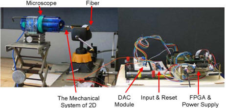
optical fiber scanning display
system. A 2D scanning display system consists of off-the-self
piezoelectric actuators and optical fiber to be further developed
into a micro display system used in HMDs for VR, AR, HUDs. An image
is produced at the viewer’s end based on persistence-of-vision from
the raster scanning motion of the actuator and the controlled
modulation of the light source.
|
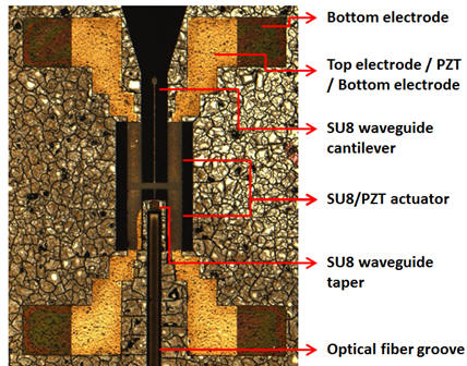
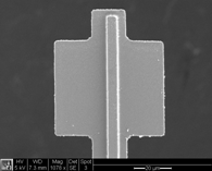
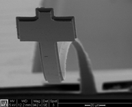
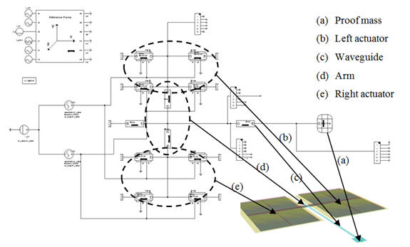
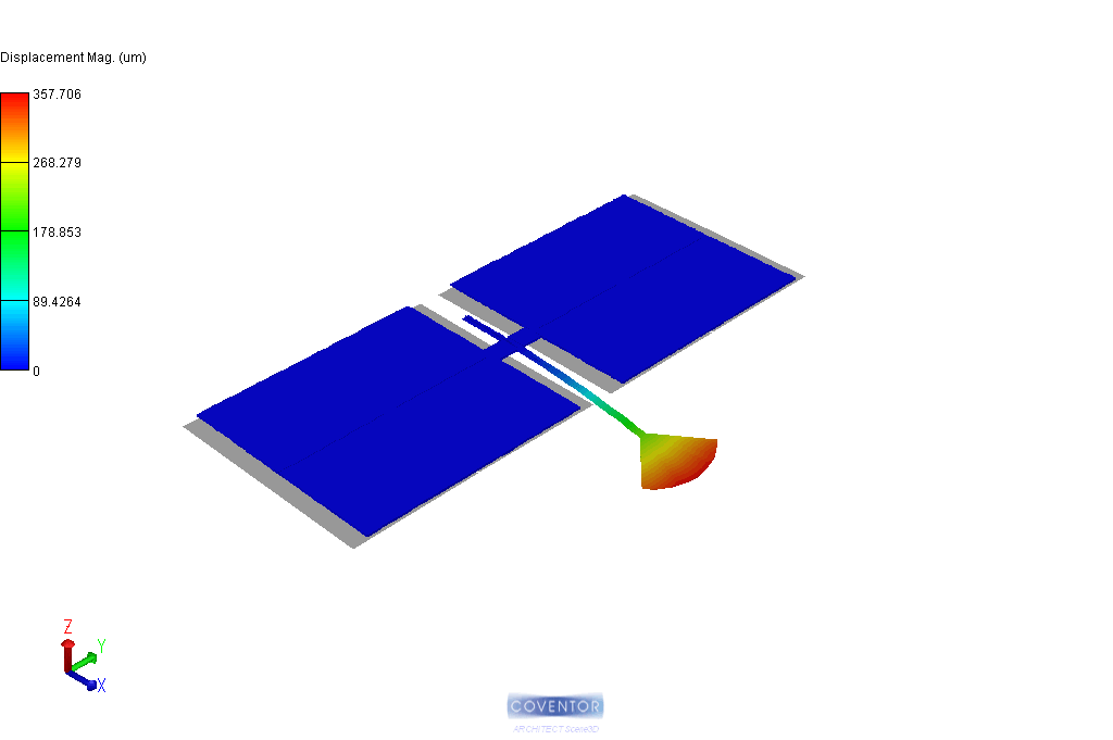
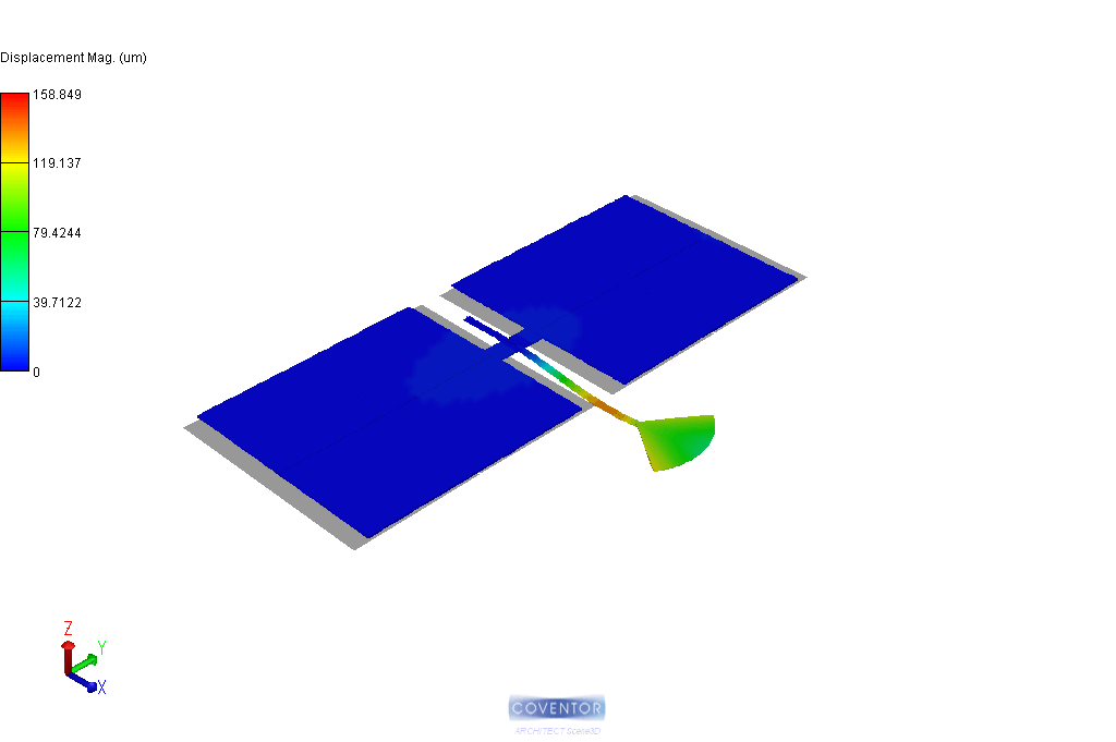
2. MEMS based mechanical scanning endoscope. Substitute a fiber with a microfabricated optical waveguide. Improved control of waveguide dimensions.Integrate actuators, light source, detectors sensors and electronics, creating a portable endoscope. Optical scanning endoscope using Microfabricated composite slab waveguide. Research ongoing with Human Interface laboratory at the Washington Technology Center, Seattle, WA.
 |
 |
 |
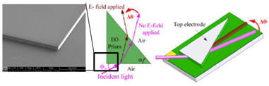
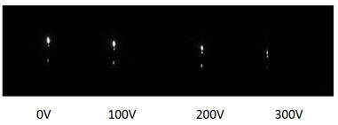
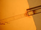
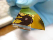
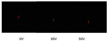
3. Electro-optic polymer based scanner. Eletro-Optic Scanner applies the voltage-driven refractive index change effect of electro-optic polymers to steer incident beam and creates a scanning motion when applied AC voltage. The main advantage of the scanner is that it has no moving parts in the system, thus eliminating mechanical fatigue, and it also allows the system to run at a higher frequencies. The system is compatible with current micro-fabrication process, making it relatively easy to produce. With a small footprint, such a system can replace the current medical imaging system such as the ones found in endoscopes and pill cameras. The scanner system can be also used as a display system when no sensor system is connected.
 |
 |
|
 |
 |
 |
4. Reduced-order modeling and fast simulation of MEMS.
MEMS are traditionally analyzed using finite element method (FEM)
and boundary element method (BEM). However, these methods have
tradeoffs in time, skill level restrictions, and limitations on the
scope of the design problem. The reduced-level models enable fast
design process with FEM accuracy.
 |
 |
 |
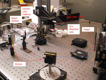
5. Holographic setup. Holography is a technique that allows the light scattered from an object to be recorded and later reconstructed so that it appears as if the object is in the same position relative to the recording medium as it was when recorded. The image changes as the position and orientation of the viewing system changes in exactly the same way as if the object were still present, thus making the recorded image (hologram) appear three dimensional. [wikipedia]
 |
 |
 |
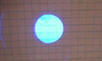
| 1. After the convex lens | 2. After the beam splitter | |
 |
 |
|
| 3. After the first mirror | 4. On target | |