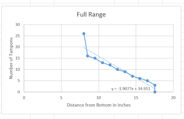
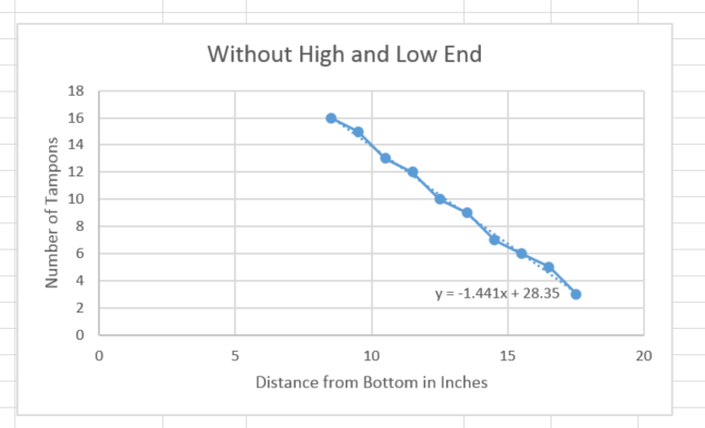
 This week I worked with the current sonic sensor to test how accurate it would be in use. The graphs above are my observations about reported distance and the number of tampons in the dispenser. I was trying to generate a function that would calculate the number without a lookup table. The first graph, it did not work out well because I included the ends, where the biggest outliers are. Removing those outliers, it gets much better. Unfortunately, this means it will be hard to tell how much product is left when the dispenser is close to empty. This sensor is unable to tell the difference between empty and 3 tampons left. I also discovered an issue where the current sensor needs about a minute of calibration time with an empty dispenser, which will be hard in the field. To this end, I began researching similar sensors and will be trying a new one in the near future.
Month: July 2015
Design: Week 2
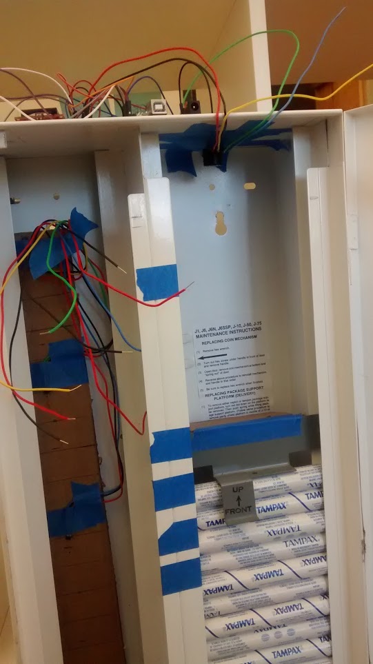
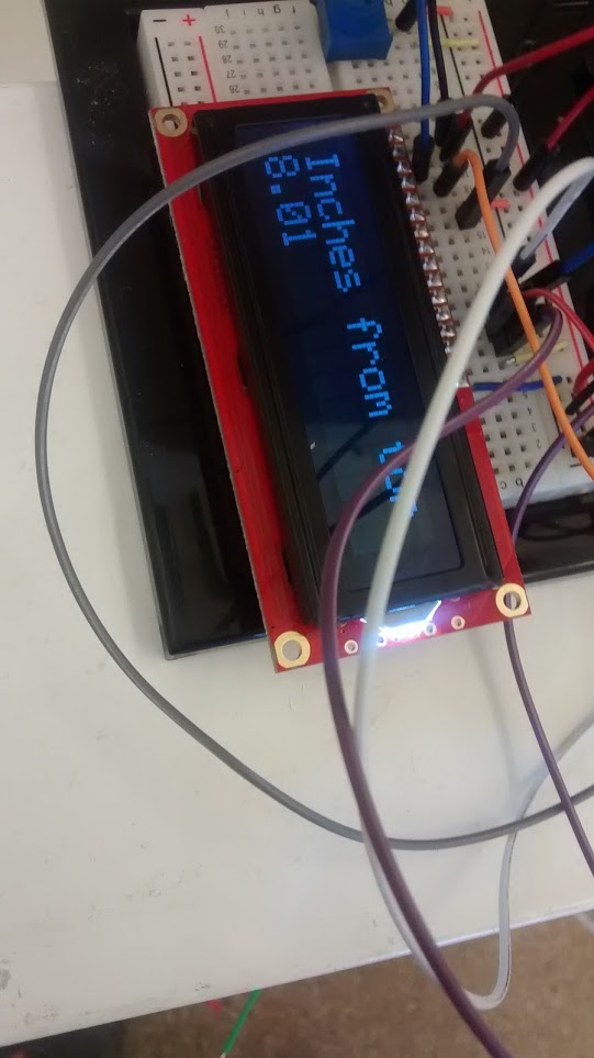
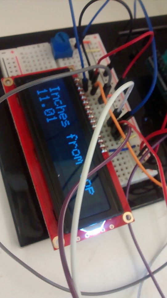

This week I successfully got the sonic sensor, which was the other option for a sensing platform, working in the casing. I soldered wires to the relevant pins of the sensor and mounted the sensor to a small piece of cardboard attached to the top of the tampon side of the dispenser. I quickly discovered that it was hard to properly line up the sonic beam to hit the weight on top of the tampons, but I solved this problem by adding some extra cardboard to the back side of the weight. This doesn’t affect the operation of the machine but makes it easier for the sonic sensor to see. After hooking up an LCD, I was able to easily see the readings from the sonic sensor. I determined that the sensor has a blind spot within about the first 9 inches or so of its reading, but after that it works like a charm and with many fewer wires and mess than the hall sensors from last week. This week, my goal is to turn the inches reporting into more relevant numbers and come up with a solution to properly handle the sonic sensor’s blind spot. Finally, I got the Pro Trinket, an Adafruit micro-controller with most of the same guts as the Arudino in a much smaller package, working (as you can see in the final image). It is harder to debug on, but it will be used in the final product due to size constraints.
Design: Week 1
Our initial supplies finally arrived a week ago, and I finally got to dig into the development for real. Below, you can see a photo of the supplies. They are organized by type: on the left you see the sensors, in the middle the micro-controllers, and on the right the communication platform (more on that at a later date). 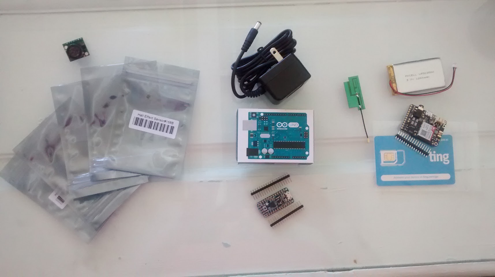
I decided to start with the Hall Effect sensors since I had never used them before and because they felt very promising. Each small bag on the left contains 1 sensor, so I had 5 to work with in all. I began by simply plugging a single sensor into a breadboard and wrote code to get that working. At first, I struggled to get the readings from the sensor to make sense because they weren’t reading reliably. After a bit of research, however, I discovered that adding a 10K pull-up resistor was the trick, and then the sensor worked beautifully.
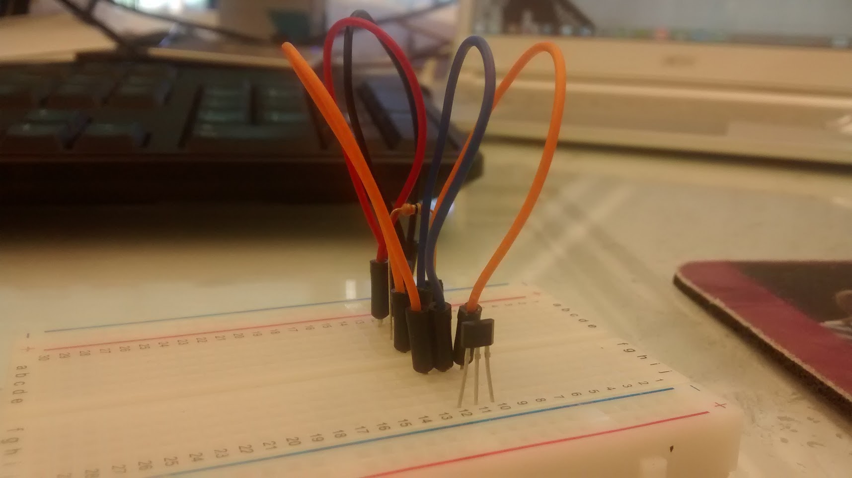
Next, I confirmed that 2 sensors would work in close proximity to each other. That went very smoothly and I discovered that the magnet has to be directly in front of the sensor to set it off, which can work well for our purposes, as long as we line up the sensors directly where the piece of metal that rest on top of the products sits.
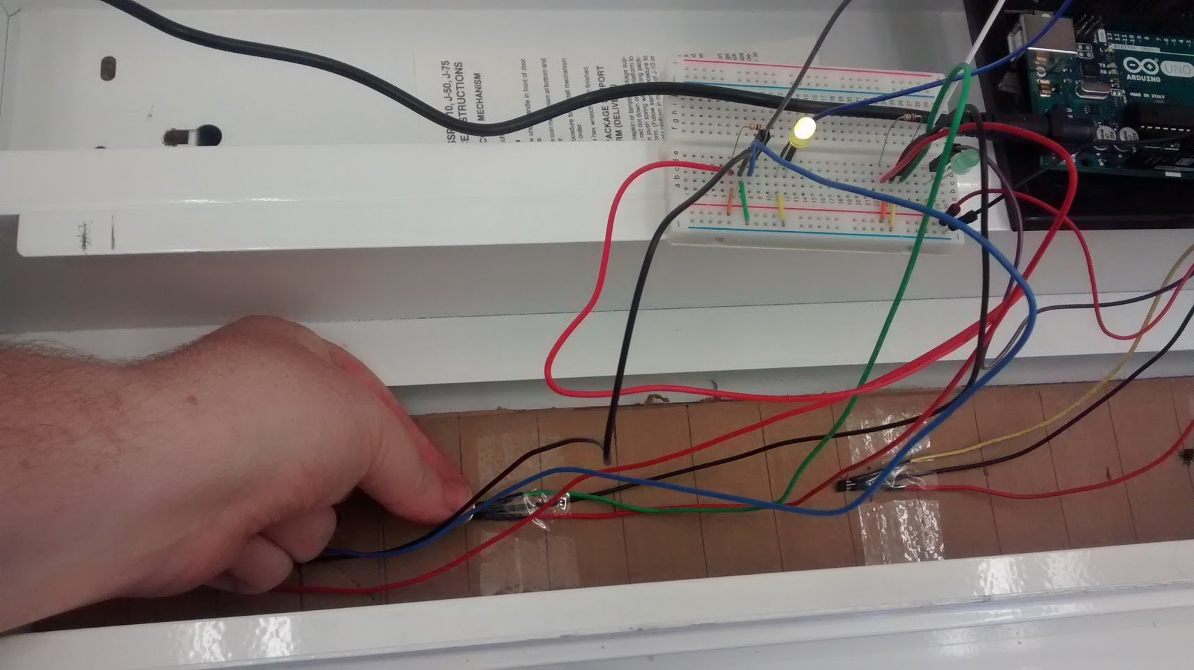
Next, I wanted to get the sensors into the dispenser itself. This required soldering long wires to the end of each sensor pin to allow them to be farther away from the Arduino and to free them from the breadboard. I also added an LED to each connection which would turn off while the sensor was being triggered so that I could more easily see the state of each sensor.
I then mounted the sensors to a long piece of recycled cardboard, which allowed me to more easily move them around and to regulate the amount of space between each sensor. This version of the prototype has a lot of wires, as you can see below. One of my goals for the next week is to work on the wire management aspect of this design. The horizontal lines on the cardboard are roughly the size of one pad box and the sensors are placed every 5 lines, except for the bottom one which would signal an empty dispenser. If there is a case where the dispenser is ever filled but not completely loaded (thus triggering the top sensor), this could present a problem for measuring the amount of product and it will have to be studied further.
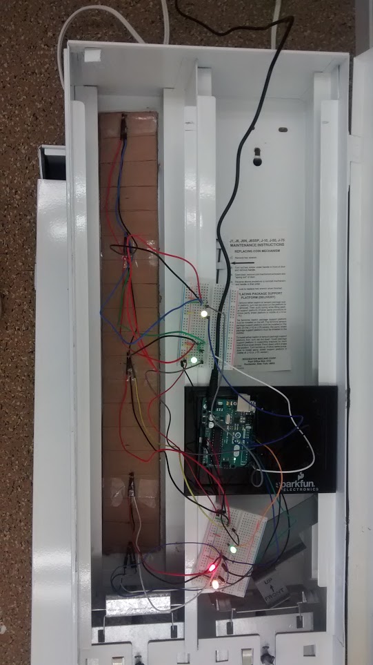
Finally, the sensor can be see in action. Notice that in the first photo, the green light on the right is on, while in the second photo it is being triggered by the sensor and is off. A video of this can be found here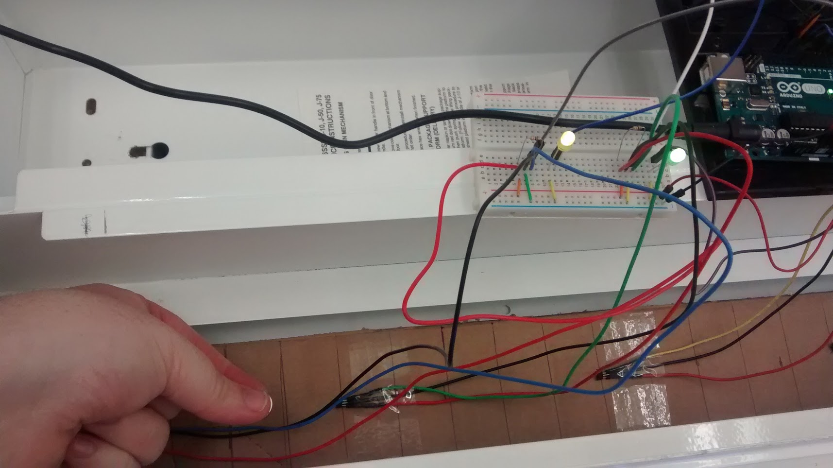
Overall, things this week went very well. The biggest lesson I learned was that I need to plan more for issues around wire management, because it can quickly get out of hand. I think now that designing the casing for this project is going to be more important than getting the sensors working. In that vein, I have begun looking into some basics of 3D printing and boards that will allow me to more permanently mount the components in the hopes of designing a robust container.