|
 |
|
|
Activity and Attenuation "objects" provide the Photon History Generator (PHG) with the spatial distribution of activity and attenuation material required for the simulation. The format of both activity and attenuation "objects" is the same and hence the term "object" will refer to either unless specific reference is necessary.
This page describes the specification and format of the objects and documents the Object Editor utility, which may be used to create them.
Coordinate system and object specification
Object dimensions and discretization are defined within the user-configurable PHG runtime parameter file. The overall dimensions of both the activity and the attenuation object must be the same for any single simulation; however, the discretization may be different in each object.
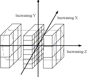
Dimensions are specified using Cartesian (x,y,z) coordinate with origin at (0,0,0) - this is the center of the tomograph axially and transaxially. The object consists of one or more axial "slices". All slices share a common horizontal and vertical size, they may vary in the axial (z) dimension. Horizontal units increase from left to right while vertical units increase from bottom to top. Units are specified in centimeters. When specifying axial dimensions you begin with the negative positions (ie those which precede the origin) and continue to stack slices towards the positive side of the origin. All dimensions are specified using two parameters, a minimum and a maximum. In figure 1 below there is a three slice object in which the outer two slices have coarser resolution than the inner slice (note that the space between slices is for illustration purposes only, object slices must be contiguous).
Figure 1. Coordinate system for SimSET "objects"
Discretization is specified by dividing each axial slice into a specific number of "voxels" in the X (horizontal) and Y (vertical) dimension The number of voxels may be different for the activity object and the attenuation object. Independent discretization in the activity and the attenution object provides optimization of memory requirements and simulation time when the resolution needs of the activity distribution are very different from the resolution requirements of the attenuation distribution.
Object cylinder
Although the object is specified in rectangular coordinates the PHG treats the object as a cylinder. Hence the "object cylinder" is the largest regular right cylinder that will fit within the rectangular parallelepiped specified in the parameter file. For the case of voxels which are only partially within the object cylinder, their entire area is used to compute decay locations; however, if the randomly selected decay location is outside of the cylinder it is discarded.
Object files
While the object specification is defined in the PHG run-time parameter file, the activity and attenuation values for each voxel are stored in separate "object files". The file format of the objects are very simple, they are binary files with one four-byte integer value for each voxel. There are no headers on these files, so as well as the object editor utility, any program that will create four-byte integer files with the appropriate number of indexes can be used to create them.
Index translation
We refer to each integer value in the object file as an "index" because it is used as a table lookup index to determine the actual value (either curies per cc for activity or mu for attenuation). The lookup process goes through a level of indirection using what we call a "translation table". This translation table is a text file which maps each possible object index to a corresponding data index which is ultimately used to retrieve the specific data value. Because object files are binary and potentially large and because the attenuation data is very large, changing the value of a particular voxel could be very difficult if this indirection where not used. Figure 2 below illustrates this process.
Figure 2. Translation tables for SimSET attenuation and activity objects. Translation tables link the indexes in the attenuation and activity objects to the SimSET data tables giving the attenuation characteristics and activity values. Here the same object is used for both the attenuation and activity object. The value 4 in the attenuation object is translated to a 3, the value for bone, in the SimSET attenuation table. The same value in the activity object is translated to the 0 mCi/cc value in the activity table.. Default index translation tables are supplied as part of the PHG package, and may be found in the phg.data directory. The standard attenuation table is called phg_att_table, and it's translation table is phg_att_table_trans. These files support attenuation values corresponding to the following materials:
Material Attenuation index 0 Water 1 Blood 2 Bone 3 Brain 4 Heart 5 Lung 6 Muscle 7 Lead 8 Sodium Iodide 9 BGO 10 Iron 11 Graphite 12 Tin 13 GI Tract 14 Connective tissue 15 Copper 16 Perfect absorber 17 LSO 18 GSO 19 Aluminum 20 Tungsten 21 Liver 22 Fat 23 LaBr3 24 Low viscosity polycarbonate 25 NEMA polyethylene 26 Polymethyl methylcrylate 27 Polystyrene fibers 28 LYSO 29 If you wish to change the default tables, we suggest you copy the distribution versions to your own working directory and edit them there. If you wish to add new materials, please contact us for information on how to do so.
Adding materials to the attenuation tables
The original programs we to generate the material tables were not written for distribution, but several users have requested them over the years. We have made a few small improvements to them and now include them in the distribution package, but they are not particularly user friendly. A little knowledge of programming may be required to use them, and we do not recommend them for novice SimSET users. You can find them in the SimSET subdirectory phg.data/material_generation. The file AddingMaterials.pdf, found in this directory, gives usage instructions.
Configuring the phg parameter file
The object editor uses the same parameter file as the PHG. Entries in this file have the following format:
DATA_TYPE parameter_name = value For example,
INT num_act_X_bins = 128
More detailed information on parameter file formats can be found in Appendix VI. Parameter type definitions for object configuration may be found below.Edit your PHG run-time parameters file and create the following entries:
Set 'point_source_voxels' = TRUE or FALSE. If TRUE, all decays are forced to occur in the center of a voxel. Typical use of this feature will be a single-voxel activity object.
Note: if the activity object has multiple voxels with activity this feature will cause each voxel to behave as if it had a point source at its center.Set 'line_source_voxels' = TRUE or FALSE. If TRUE, the specified activity for the voxel is "distributed" along an infinitely thin line projected axially through the center of the voxel.
Note: as with point_source_voxels, if the activity object has multiple voxels with activity this feature will cause each voxel to behave as if it had a line source at it's center.Set 'object' = 1+the number of object slices required
Set 'num_slices' = the number of slices required
For each slice:
Set 'slice' = 9 (if you are using the same discretization for the activity and attenuation objects)
'slice' = 11 (if you are using different discretization for the activity and attenuation objects)Set 'slice_number' = number_of_this_slice (slice numbers start at zero and are contiguous)
Set 'zMin' = the starting z-axis position of this slice
Set 'zMax' = the ending z-axis position of this slice
Set 'xMin' = the starting x-axis position of this slice
Set 'xMax' = the ending x-axis position of this slice
Set 'yMin' = the starting y-axis position of this slice
Set 'yMax' = the ending y-axis position of this slice
If you are using the same discretization for activity and attenuation objects:
Set 'num_X_bins' = number of horizontal bins for the activity and attenuation objects
Set 'num_Y_bins' = number of vertical bins for the activity and attenuation objects
If you are using different discretization for activity and attenuation objects:
Set 'num_act_X_bins' = number of horizontal bins for the activity object
Set 'num_act_Y_bins' = number of vertical bins for the activity object
Set 'num_att_X_bins' = number of horizontal bins for the attenuation object
Set 'num_att_Y_bins' = number of vertical bins for the attenuation object
After specifying the object geometry the following parameters must also be defined:
Set 'activity_indexes' to the name of the activity index file (you can use the object editor to create one)
Set 'attenuation_indexes' to the name of the attenuation index file (you can use the object editor to create one)
NOTE: The activity/attenuation translation tables and their respective index translation tables are not necessary for creating the index files with the object editor. These files are only used by the PHG module.
[top of page] [example parameter files]
The Object Editor
Using the Object Editor
The object editor is an interactive command-line program. You execute it by entering the name of the executable, MakeIndexFile by default, followed by the name of the PHG parameter file you are going to use. The object editor will then present a series of questions allowing you to create your activity and or attenuation files. The questions asked by the object editor are listed below in the order in which they appear:
Build indexes for "your_activity_index_file_name" (Yes..No) [Yes]:
You have the option of creating indexes for either the activity index file, the attenuation index file, or both. Answering "yes" here will initiate the process of creating the activity object.
Assuming you answered "yes" to the previous question:
Would you like to fill the entire object with a single value? (Yes..No) [Yes]:
Normally you will want to set all voxels to a background level. Commonly this value will be zero indicating no activity or air. Note that if you are simulating the simplest geometry, a single voxel cylinder, then this is the only value you need to specify.
Assuming you answered "yes" to the previous question:
Enter fill value for object (0..255):
Enter the index value you want to use as background. Every voxel in the object will be set to this value. Later specifications may overwrite this initial value.
Would you like to fill the entire object from a single data file? (Yes..No) [No]:
If you have an existing file, such as a digital phantom like the Zubal Whole Body Phantom, you can use this to initialize your object. Enter the name of the file here.
Assuming you answered "yes" to the previous question:
Enter offset (in bytes) to start of data:
You can index into any byte offset within the file. For instance, you might use this to skip over a header.
Enter offset (in bytes) between slices of data:
If the digital phantom is orientated in axial slices, and there is a per-slice header, enter the size of this header here.
Enter size of indexes (as in 1 byte, 2 bytes, 4 bytes = 1,2 or 4):
Enter the byte size of the digital phantom indexes.
The object will now be initialized according to the digital phantom data. Note that you must have as many slices in the digital phantom as you have in the object to use this option. If you do not, for instance if you want to initialize only certain slices from digital data, then use the options below.
Would you like to initialize specific slice values? (Yes.No) [No]:
Regardless of whether you filled the object above, you can now specify values on a slice-by-slice basis.
Assuming you answered "yes" to the previous question:
Do you have a prepared file for slice n? (Yes..No) [No]:
If you are going to use this option, then the process is the same as above for filling the entire object. You can use pre-existing files or specify individual values.
We will skip to the next section:
Would you like to create an 'object'? (Yes..No) [Yes]:
You now are given the option of creating an 'object'. The editor can generate simple geometric objects and set them to specific values. Note that for any objects which overlap, the most recently specified value will be assigned to the overlapping voxels.
Assuming you answered "yes" to the previous question:
Select a type (cylinder, sphere, voxel) [cylinder]:
The object editor is capable of creating four kinds of objects, the first three are displayed in the prompt. The fourth, is a parallelepiped, and is accessed by entering 'box'. For each geometric shape a series of questions is presented in order to define the dimensions of the object. An example of creating a cylinder is now provided:
Please select a center point for the cylinder
Enter x-axis coordinate:
Enter y-axis coordinate:
Enter z-axis coordinate:
Enter the center point of the cylinder in (x,y,z) Cartesian coordinates. Units are in centimeters just as the definition of the object.
Enter the length along z-axis:
Enter the length of the cylinder. The cylinder will be centered over the z-axis coordinate specified above.
Enter the x-axis radius:
Enter the y-axis radius:
Enter the radius in the x and y dimension. Although the object cylinder is a regular right cylinder, internal cylinders may be eliptical.
Enter the fill value for object (0..255):
Enter the index value for the object. The editor will display the number of voxels filled. This can be used to verify the object is represented adequately by voxelization selected.
Would you like to create another 'object'? (Yes..No) [No]:
You may repeat the process above as many times as necessary. When you are finished created objects, just answer 'No'.
Build indexes for "your_attenuation_index_file_name" (Yes..No) [Yes]:
The process above will be repeated to create your attenuation index file.
At this point the activity and attenuation files have been created. If the remaining parameter files are complete, the simulation may be run at this point.
Using Pre-Existing Image Data
The object editor facilitates the use of pre-existing image data (digital phantoms). We have tried to anticipate the most common formats that these files might adhere to. Hence the questions asked when you specify that you do wish to fill your object from a pre-existing file help the object editor interpret the format. They are described in more detail below:
Would you like to fill the entire object from a single data file? (Yes..No) [No]:
Enter the name of the pre-existing image data file here.
Enter offset (in bytes) to start of data:
You can index into any byte offset within the file. This allows you to skip over initial headers and/or unwanted slices. The value of the offset is "bytes".
Enter offset (in bytes) between slices of data:
If the digital phantom is orientated in axial slices, and there is a per-slice header, enter the size of this header here. This will cause the object editor to automatically skip over this number of bytes per slice (of object data).
Enter size of indexes (as in 1 byte, 2 bytes, 4 bytes = 1,2 or 4):
Enter the byte size of the digital phantom pixel values.
The object will now be initialized according to the digital phantom data. The first option, "fill the entire object from a single data file" requires that the data file have at least as much pixel data as the object. If you wish to fill only certain slices from your pre-existing data, then answer no to the prompt, a subsequent prompt will ask if you wish to fill specific slices from pre-existing data.
Parameter type definitions for object section in PHG parameters file
Technically, the object editor does not require that all of the parameters necessary for the PHG be present in the parameters file. The following table illustrates all of the parameters necessary to create activity and attenuation objects.
Parameter name units data type point_source_voxels
BOOL line_source_voxels
BOOL object
NUM_ELEMS_IN_LIST num_slices
INT slice
NUM_ELEMS_IN_LIST slice_number
INT
(starts at zero, slice numbers must be contiguous)zMin cm REAL zMax cm REAL xMin cm REAL yMin cm REAL yMax cm REAL num_X_bins
INT num_Y_bins
INT num_act_X_bins
INT num_act_Y_bins
INT num_att_X_bins
INT num_att_Y_bins
INT activity_indexes
STR
User supplied name of activity index file to be createdattenuation_indexes
STR
User supplied name of attenuation index file to be created
The following examples are complete PHG run-time parameter files - the section of interest is labelled "OBJECT GEOMETRY VALUES"
Example 1 - Object of axial length 20 cm containing a single slice with just one voxel. This is an efficient way to simulate a uniform cylindrical phantom. The radius of the object cylinder is 5 cm and it is centered on the center of the tomograph.
Note that 'num_act_X_bins', 'num_att_X_bins', 'num_act_Y_bins' and 'num_att_Y_bins' are not present - only the variables 'num_X_bins' and 'num_Y_bins' have been used. The effect of this is to define the same discretization for the activity and the attenuation objects.
Example 2 - Object of axial length 20 cm divided into a 9 cm slice, a 2 cm slice and another 9 cm slice. The object cylinder has a radius of 5 cm. The slices are symmetric about the center of the tomograph. The central slice is high resolution (128x128 voxels), allowing a detailed description of the activity and attenuation in this region - the outer slices contain just one element, so that the activity and attenuation distribution there will be uniform.
Example 3 - Object containing 12 slices. Each slice has an axial thickness of 4 cm, and transaxial dimensions 64x64 cm. There are 128x128 voxels in each slices, so that the voxel size is 4.0 cm x 0.5 cm x 0.5 cm. These parameters could be used to define a complex torso-sized activity and attenuation object.
This page has more information regarding the relationship between what is produced using MakeIndexFile, and how the PHG interprets that.
| Last revised by: | Robert Harrison |
| Revision date: | 11 April 2011 |