|
 |
|
|
Overview
The Photon History Generator (PHG) is a software application designed to perform Monte-Carlo simulations of photon creation and transport through heterogeneous attenuators for both SPECT and PET. When we refer to "SimSET", we are generally referring to the entire software package: all tracking modules, the binning module, and all utilities that are included. When we refer to the "PHG" we are specifically referring to the Photon History Generator module of SimSET. The PHG module generates photons and transports them through the "object" (see object editor page) to the face of the collimator or detector. This page documents the PHG module of SimSET.
The figure below provides an interactive "black-box" view of the PHG, defining all of the input data and output data used and created by the PHG. If you run into trouble with the pop-ups or get JavaScript errors, try reloading the page. All the textual data associated with the figure is included in tabular form below for printing purposes.
Figure 1: PHG inputs and outputs.
[top of page][functional description][configuration][coherent scatter][positron range][examples]
PHG inputs
| Activity Distribution | This file defines the distribution of isotope being simulated. It is created by the object editor. |
| Attenuation Distribution | This file defines the distribution of attenuating material being simulated. It is created by the object editor. |
| Simulation Options | These options are specified in a text file referred to as the PHG run-time parameters and often abbreviated as phg_params. These options are defined individually, below. |
| Data Tables | These tables are supplied with the PHG package. They provide information for operations like importance sampling and scatter modeling. The tables are defined individually below. |
PHG outputs
| Binned Data | Tracked photons may be passed to the Binning Module, where they are sorted into sinograms, projections or other histogram formats as specified by the user. Photons may also be sorted by energy and scattering history. |
| Statistical Summary | Regardless of what parameters are specified, and what type of simulation is run, the PHG produces detailed statistical information which provides a summary of the simulation results. |
| Photon History List | The Photon History List. contains a decay record followed by a photon record(s) for each photon that reaches the Target Cylinder and satisfies the user-specified criteria. Refer to the History File page for a full description of this output. |
| Productivity Table | This table is used for the importance sampling technique of stratification. It also appears in the Data Tables section below because once created, it is then used as input data for subsequent simulations. |
| Simulation Summary | This is information printed on the screen during the simulation. It provides a detailed description of the input parameters used in the simulation. It also provides a summary of the number and weights of photons entering and being accepted by each module. Within a given module certain characteristic information may also be printed. |
[top of page][functional description][configuration][coherent scatter][positron range][examples]
The Photon Tracking Algorithm
The PHG calculates the number of decays to generate for each voxel from the Activity Object and the simulation parameter 'num_to_simulate'. The figure below illustrates the control flow for tracking photons.
Figure 2: Control Flow for Tracking Photons.
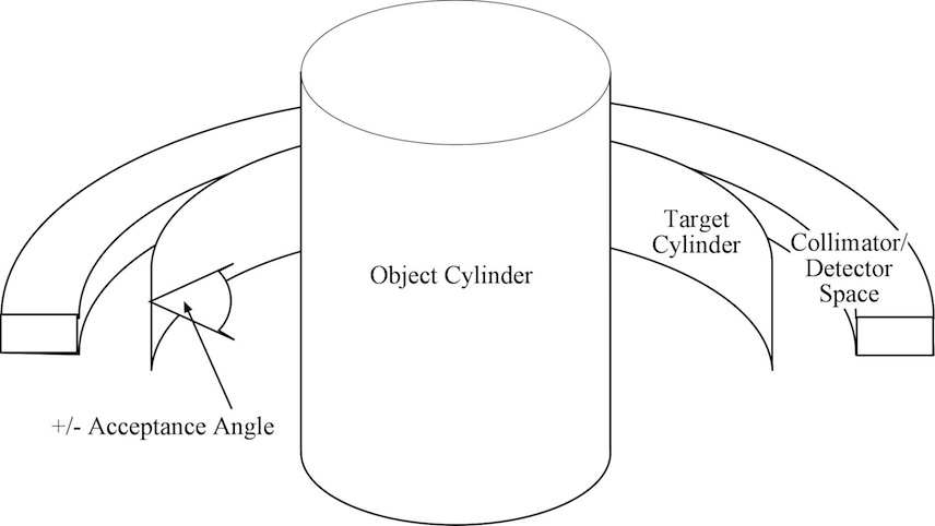
Each photon is tracked from its starting location to the surface of the Object Cylinder. From there, the photon is projected to a bounding cylinder referred to as the Target Cylinder. The radius and axial extent of the Target Cylinder are user-specified; they will usually be determined by the radius and axial dimensions of the detection/collimation system to be simulated. The space between the Object Cylinder and Target Cylinder is modeled as a vacuum. All photons that reach the Target Cylinder within a user-specified axial Acceptance Angle will be passed on to the collimator/detector/binning modules and/or included in the PHG history file, depending on the PHG run-time parameter file. The "Tracking Photons" flow chart includes a "Collimate Photon" and "Detect Photon" step. These steps are described in separate manual pages. They are included in the diagram for completeness even though they exterior SimSET modules distinct from the PHG.
A simplified conceptual model of the tracking algorithm is presented below:
- Sample an initial direction vector for the photon.
- Sample the number of free-paths to travel before an interaction occurs.
- Calculate the travel-distance corresponding to the selected free-paths, the attenuation values for all voxels encountered, and the distance traveled through each voxel.
- If the photon reaches the Object Cylinder without interacting, and it satisfies the acceptance criteria, add it to the Photon History List. Otherwise, choose a scatter angle and corresponding energy value, and continue tracking.
Note: the photon is projected from the surface of the Object Cylinder to the surface of the Target Cylinder before selection criteria are applied.
[top of page][functional description][configuration][coherent scatter][positron range][examples]
Importance sampling
SimSET incorporates several importance sampling (also called variance reduction) options (Haynor et al, 1990, Haynor et al, 1991) into photon tracking. We give a brief description of SimSET's implementation here; for more details on both implementation and theory, please see the references.
The PHG uses three main importance sampling techniques, stratification, forced detection, and forced non-absorption. Instructions on how to use them are given below. Another importance sampling technique, forced interaction, is used in the detector module.
Importance sampling is a way of accelerating convergence of the estimates of SimSET's histogrammed output. When stratification is used, the PHG chooses decay locations and initial photon directions that are likely to be detected with a higher probability than they would normally be sampled (figure 3). When forced detection is used, copies of photons are forced to scatter toward the tomograph somewhere within the volume visible to from the tomograph, and copies of photons within this volume are forced to pass through the attenuation to the tomograph (figure 4). With forced non-absorption, when photons interact in the object they always scatter - they are not allowed to be photoelectrically absorbed. In all cases this is done without biasing the output histograms. The main tools are photon and decay weights: when a decay location, photon direction or interaction is oversampled, the corresponding weight decreased in proportion to the oversampling. Conversely, when undersampling occurs the corresponding weight is increased. In a sense these weights tell us how many 'real world' decays or photons the simulated decays and photons represent. Thus, when histogramming one needs to histogram weights rather than counts.
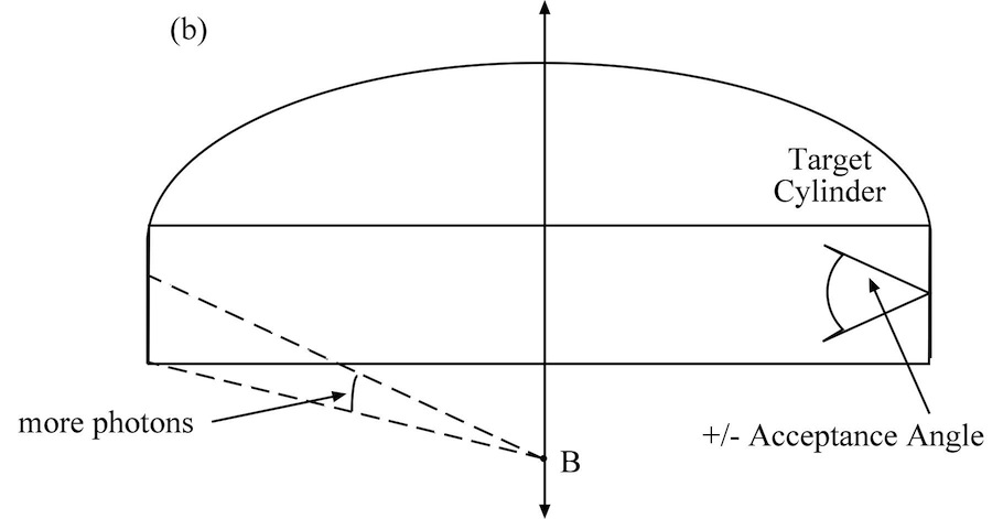
Figure 3. Stratification. (a) More decays are simulated at locations where they are likely to lead to detected locations than at locations where they arent. For instance, if voxels A and B have the same activity, more decays will be simulated in voxel A than B: decays in the field-of-view are more likely to be detected. (b) Once a decay location is selected, the photon direction is also stratified. Photon directions that will intersect the target cylinder within the acceptance angle are sampled more heavily than ones that wont.
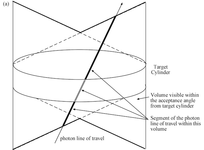
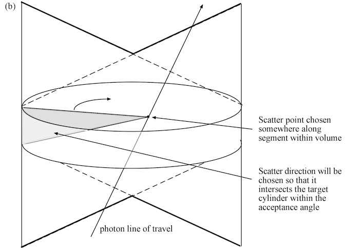
Figure 4. Forced detection. (a) When a photon will pass through the volume visible from the target cylinder, a copy of the photon is made. (b) This copy is then forced to scatter somewhere in this volume. The photon direction after the scatter is chosen so that it will hit the target cylinder within the acceptance angle. Once the forced detection is complete, regular tracking of the original photon is resumed.
[top of page][functional description][configuration][coherent scatter][positron range][examples]
The PHG uses a parameter file to select simulation options, configure the activity and attenuation object, define the target cylinder and to select data table files. The PHG run-time parameter file (often abbreviated to phg_params or run_params ) is an ascii text file consisting of entries of the following format:
DATA_TYPE parameter_name = value For example,
BOOL simulate_stratification = TRUE
More detailed information on parameter file formats can be found in Appendix VI. Parameter type definitions for the PHG run-time parameters file may be found below.To configure the PHG for a simulation, edit (or create) a PHG run-time parameters file as follows:
Simulation Options
Create entries for each of the simulation options described in table 3 below:
| General simulation options | |
| num_to_simulate | Specifies the number of decays to simulate. The photon weight is determined as a factor of this number, the length of the scan, and the amount of "activity" which is specified for the voxel in which the photon originates. To have the number of simulated decays determined from the activity and length of scan, set num_to_simulate = 0; this is required for simulations that will include randoms. Please note that even a small amount of activity produces a very large number of decays per second and can result in a very long simulation. |
| length_of_scan | Specifies the time to simulate in seconds. The default is 60 seconds. Unless num_to_simulate = 0 (see above), the photon weight is determined as a factor of this number, the number of decays, and the amount of "activity" which is specified for the voxel in which the photon originates. |
| simulate_SPECT | If set TRUE, the simulation produces single photons. If FALSE, or if simulate_SPECT is not included in the parameter file, then one of simulate_PET_coincidences_only or simulate_PET_coincidences_plus_singles must be set TRUE. |
| simulate_PET_coincidences_only | If set TRUE, the simulation models positron range, if desired, then an annihilation producing two (nearly) collinear photons traveling in opposite directions. If one annihilation photon is discarded (e.g., is absorbed in the object or collimator or goes off in an undetectable direction) then the simulation will cease tracking the other photon; this option is thus incompatible with randoms generation. If this option is set FALSE, or if simulate_PET_coincidences_only is not included in the parameter file, then one of simulate_SPECT or simulate_PET_coincidences_plus_singles must be set TRUE. |
| simulate_PET_coincidences_plus_singles | If set TRUE, the simulation models positron range, if desired, then an annihilation producing two (nearly) collinear photons traveling in opposite directions. This is the correct simulation option to use in simulations that will include randoms generation; in contrast to simulate_PET_coincidences_only, if one photon from an annihilation is discarded, the simulation continues to track the single photon. If this option is set FALSE, or if simulate_PET_coincidences_plus_singles is not included in the parameter file, then one of simulate_SPECT or simulate_PET_coincidences_only must be set TRUE. |
| photon_energy | The initial energy of photons in units of "keV". |
| minimum_energy | A cut-off value, simulation is discontinued for photons whose energy drops below this value (as a result of Compton interactions) as they traverse the object and collimator. This value should be enough below the energies of interest (e.g., the lowest histogrammed energy) that a photon at the minimum energy is unlikely to be of interest even if it deposits its full energy in the detector, remembering that the detected energy may be greater than the photon energy due to imperfect energy resolution. |
| model_coherent_scatter_in_obj | Specify whether or not coherent scatter is modelled as a part of the photon interaction modeling process during tracking through the object. In order to use this feature the source of the angular distribution data must be specified below in the parameter, coherent_scatter_table. Currently if simulate_forced_detection is set TRUE, SimSET requires that model_coherent_scatter_in_obj is set FALSE. Note that at energies greater than about 200 keV in soft tissue and 300 keV in bone, less than one per cent of photon interactions are coherent scatter. |
| model_coherent_scatter_in_tomo | Specify whether or not coherent scatter is modelled as a part of the photon interaction modeling process during tracking through the collimator and detector. In order to use this feature the source of the angular distribution data must be specified below in the parameter, coherent_scatter_table. Note that coherent scatter is considerably more likely in high-Z materials, like septa and detector crystal, than in biological tissues. We recommend that model_coherent_scatter_in_tomo be set TRUE. |
| adjust_for_collinearity | (PET simulations only) Specifies whether or not "non-collinearity" is modelled for the photons resulting from a positron annihilation. If set false, the annihilation photons will travel collinearly, with their directions 180 degrees apart. If set TRUE, one of the annihilation photons will be deflected so that the angle between the two photon paths is distributed as a Gaussian random variable with mean 180 degrees and standard deviation 0.5 degrees. |
| adjust_for_positron_range | Specifies whether or not "positron range" is modelled. You must specify an isotope, and a data file for the parameter "isotope_data_file. For more information see using positron range. An example for doing this with the default table is:
ENUM isotope = C11 STR isotope_data_file = "/simset/phg/phg.data/isotope_positron_energy_data" |
| random_seed | Normally this value should be omitted or set to 0. For debugging purposes only, set this value to a non-zero, positive value to use a reproducible seed to initialize the random number generator. If omitted or left zero, the seed will be taken from the system clock and will be unique for each simulation performed. |
| Importance sampling options | |
| simulate_stratification | Specifies whether or not the importance sampling technique of "stratification" is applied to the simluation. When stratification is used, those outcomes which are more likely to result in a detected photon are sampled more frequently, and a weight is associated with each outcome to avoid bias.
In order to use this feature you must perform two simluations, the first creates a "productivity table" which the second utilizes to reduce simulation time. For the first run:
Then for the second run:
|
| simulate_forced_detection | Specifies whether or not the importance sampling technique of "forced detection" is applied to the simulation. If set TRUE, when photons scatter in the object, the scatter angle is forced to be in the direction of the detectors, and the photon weight is appropriately modified to avoid bias. |
| forced_non_absorption | Specifies whether or not the importance sampling technique of "forced non absorption" is applied to the simulation. If set to TRUE modeling of photon interactions prevents absorption as an outcome. Photons which would undergo absorption in a "normal" simulation undergo a weight modification and continue to be tracked. |
| weight_window_ratio | A parameter for "forced detection" which helps to reduce the variance of photon weights undergoing forced detection (set to range 1-3 ). If the weight window ratio is set to 1, no weight windowing is done. |
Table 3: Simulation options
[top of page][functional description][configuration][coherent scatter][positron range][examples]
Target Cylinder
After tracking a photon through the object cylinder, the PHG uses a target cylinder to determine whether the photon should be sent to the collimator/detector/binning modules, and/or saved in a PHG history file. Only photons that hit the radial surface (as opposed to the end surfaces) of the target cylinder with an inclination angle less than an acceptance angle are passed on. In cases where a binning parameters file is specified, but no collimator or detector are specified, events will be histogrammed based on photon position on the target cylinder.
The coordinate system for the target cylinder has the same orientation as the object cylinder - the origin lies at the center of the tomograph, and the Z-axis is parallel to the tomograph axis. In the parameters file, the min and max Z and the radius of the target cylinder need to be specified:
The target cylinder must sit somewhere between the object cylinder and the collimation/detection system. Making it the innermost surface of the collimator often makes the most sense.
The acceptance angle is intended to eliminate the further processing of some photons that have no chance of being detected, improving the simulation efficiency, particularly when using importance sampling. When using a perfectly absorbing or geometric collimator, there is some maximum axial angle at which a photon can pass through the collimator. This should be used as the acceptance angle. In cases where scatter off the collimator is being modeled, the acceptance angle should be set to 90 degrees. In simulations in which no collimation or detection is specified, the acceptance angle can be used to approximate perfect collimation.
NOTE: Any space between the object cylinder and the target cylinder will be modelled as a vacuum.
Target Cylinder target_cylinder Set to 3: indicates the number of parameters in the list defining the target cylinder. target_zMin The minimum Z extent of the target cylinder. target_zMax The maximum Z extent of the target cylinder. radius Radius of the target cylinder. acceptance_angle An optimization parameter which rejects photons which reach the target cylinder with an angle-of-incidence too great to be detected. This can be used as a perfect collimator.
Warning: If you change your object, but keep the same phg parameters (or vice-versa), remember to change your acceptance angle!Table 4: Target cylinder definitions
Activity and Attenuation Object Specification
The geometry and discretization of the activity and attenuation objects are specified in the PHG run-time parameters file - the relevant parameters for this are described in detail in the object editor page.
[top of page][functional description][configuration][coherent scatter][positron range][examples]
Data Tables, Parameter Files, and Output Files
Create entries for each of the data tables, parameter files, and output files described in table 5 below:
| coherent_scatter_table | Specifies the name of the data file containing the angular distribution
data for modeling coherent scatter. This file must be
supplied if model_coherent_scatter_in_obj and/or model_coherent_scatter_in_tomo
are set TRUE. Use the SimSET-supplied table unless specific
alteration is desired.
Standard location: "/phg/phg.data/phg_ad_files" The phg_ad_files is a text file that must be modified to your system's pathnames before running. |
| isotope_data_file | Specifies the name of the isotope data file used for positron range
simulations.
This file must be
supplied if adjust_for_positron_range
is set TRUE. Use the SimSET-supplied table unless specific
alteration is desired.
Standard location: "/phg/phg.data/isotope_positron_energy_data" |
| Object activity specification | |
| activity_indexes | Specifies the name of the activity object index values. This file can be created by the object editor. |
| activity_table | Specifies the name of the activity table file which is used to convert activity indexes into actual isotope concentration values. Use the table supplied unless specific alteration is desired.
Standard location: "/phg/phg.data/phg_act_table" |
| activity_index_trans | Specifies the name of the activity index translation file which is used to change the one-to-one mapping of index values in the object file with activity concentrations in the activity table. See the object_editor page for full details.
Standard location: "/phg/phg.data/phg_act_index_trans" |
| activity_image | Specifies the name of the activity image output file. This file contains the actual isotope concentration levels for each voxel in the activity object. It can be used primarily for image display or special analysis purposes, it is not used by the simulation software. |
| Object attenuation specification | |
| attenuation_indexes | Specifies the name of the attenuation object index values. This file can be created by the object editor. |
| attenuation_table | Specifies the name of the attenuation table file which is used to convert activity indexes into actual attenuation values. Use the table supplied unless specific alteration is desired.
Standard location: "/phg/phg.data/phg_att_table" |
| attenuation_index_trans | Specifies the name of the attenuation index translation file which is used to change the one-to-one mapping of index values in the object file with attenuation values in the activity table. See the object_editor page for full details.
Standard location: "/phg/phg.data/phg_att_index_trans" |
| attenuation_image | Specifies the name of the attenuation image output file. This file contains the actual attenuation levels for each voxel in the attenuation object. It can be used primarily for image display or special analysis purposes, it is not used by the simulation software. |
| Importance sampling files | |
| productivity_input_table | Specifies the name of the productivity table to be used when "stratification" is being applied. This file is created automatically by turning stratification on and specifying a name in the parameter "productivity_output_table" described below. |
| productivity_output_table | Specifies the name of the productivity output file name. This file is produced when stratification is being applied to the simulation. It is a text file which can be edited directly if desired but this should never be necessary. |
| Parameter files for other modules | |
| collimator_params_file | Specifies the name of the parameters file for the collimator module. If this parameter is left blank no collimator modeling is performed. |
| detector_params_file | Specifies the name of the parameters file for the detector module. If this parameter is left blank no detector modeling is performed. |
| bin_params_file | Specifies the name of the parameters file for the binning module. If this parameter is left blank no on-the-fly binning is performed. This parameter can be specified up to twelve times using unique parameter file names to implement different binning options simultaneously during one simulation. (We have had reports that the multiple binning files feature is misfunctioning intermittently. We have not yet determined under what circumstances this occurs. We suggest using the new tomograph file feature instead until we have tracked down the problem.) |
| tomograph_params_file | Specifies the name of a tomograph parameter file. Using tomograph_params_file replaces the collimator_params_file, detector_params_file, and bin_params_file. The collimator, detector and binning parameters files are instead specified in the tomograph parameter file. Up to 100 tomograph files can be specified in a single run file, allowing multiple tomographs to be simulated at one time. |
| PHG history file specification | |
| history_file | Specifies the name of the parameters file for the history module. If this parameter is left blank no history file is created. |
| history_params_file | Specifies the name of the parameters file for customizing the history file. If this parameter is left blank the default history file format is applied. |
| Miscellaneous | |
| statistics_file | Specifies the name of the statistics output file. This file is used for debugging purposes only and should never be used for analyzing the results of an actual simulation. |
[top of page][functional description][configuration][coherent scatter][positron range][examples]
Parameter type definitions for PHG parameters file
| Parameter name | units | data type |
| Simulation Options: | ||
| num_to_simulate | LONGLONG (also accepts INT, though this limits the number of decays to < 2x10^9) | |
| length_of_scan | seconds | REAL |
| simulate_SPECT | BOOL | |
| simulate_PET_coincidences_only | BOOL | |
| simulate_PET_coincidences_plus_singles | BOOL | |
| photon_energy | keV | REAL |
| minimum_energy | keV | REAL |
| model_coherent_scatter_in_obj | BOOL | |
| model_coherent_scatter_in_tomo | BOOL | |
| adjust_for_collinearity | BOOL | |
| adjust_for_positron_range | BOOL | |
| isotope | ENUM (see Using Positron Range Modeling for acceptable values) | |
| random_seed | INT | |
| Importance Sampling: | ||
| simulate_stratification | BOOL | |
| simulate_forced_detection | BOOL | |
| forced_non_absorption | BOOL | |
| weight_window_ratio | REAL | |
| Object Geometry/Object Cylinder: | See Object Editor page for more information | |
| point_source_voxels | BOOL | |
| line_source_voxels | BOOL | |
| object | NUM_ELEMS_IN_LIST | |
| num_slices | INT | |
| slice | NUM_ELEMS_IN_LIST | |
| slice_number | INT (starts at zero, slice numbers must be contiguous) |
|
| zMin | cm | REAL |
| zMax | cm | REAL |
| xMin | cm | REAL |
| yMin | cm | REAL |
| yMax | cm | REAL |
| num_X_bins | INT | |
| num_Y_bins | INT | |
| num_act_X_bins | INT | |
| num_act_Y_bins | INT | |
| num_att_X_bins | INT | |
| num_att_Y_bins | INT | |
| Target Cylinder: | ||
| target_cylinder | NUM_ELEMENTS_IN_LIST | |
| target_zMin | cm | REAL |
| target_zMax | cm | REAL |
| radius | cm | REAL |
| acceptance_angle | degrees | REAL |
| Data Tables, Parameter Files and Outputs: | ||
| coherent_scatter_table | STR | |
| isotope_data_file | STR | |
| Activity Object: | See Object Editor page for more information | |
| activity_indexes | STR | |
| activity_table | STR | |
| activity_index_trans | STR | |
| activity_image | STR | |
| Attenuation Object: | See Object Editor page for more information | |
| attenuation_indexes | STR | |
| attenuation_table | STR | |
| attenuation_index_trans | STR | |
| attenuation_image | STR | |
| Importance Sampling: | ||
| productivity_input_table | STR | |
| productivity_output_table | STR | |
| Parameter files for other modules: | ||
| collimator_params_file | STR | |
| detector_params_file | STR | |
| bin_params_file | STR | |
| tomograph_params_file | STR | |
| History file parameters: | ||
| history_file | STR | |
| history_params_file | STR | |
| Miscellaneous: | ||
| statistics_file | STR |
[top of page][functional description][configuration][coherent scatter][positron range][examples]
SimSET allows modeling of coherent scatter to be turned on or off. This is done separately for modeling of coherent scatter in the object and for modeling of coherent scatter in the tomograph (the collimator and detector). Use of forced detection is not compatible with modeling of coherent scatter in the object in SimSET's current version.
Coherent scatter occurs mainly at low energies and in high-Z materials (in general materials with a high atomic number). Less than one per cent of photon interactions are coherent scatter at energies greater than about 200 keV in soft tissue and 300 keV in bone. In lead, tungsten, and typical detector materials, more than one percent of interactions are coherent scatter even at positron annihilation photon energy (511 keV). Therefore we recommend that coherent scatter modeling is always used in the tomograph. We also recommend that coherent scatter modeling is used in the object unless forced detection is being used - it slightly improves simulation accuracy and has little effect on efficiency.
The boolean parameters model_coherent_scatter_in_obj and model_coherent_scatter_in_tomo are used to turn coherent scatter modeling on or off. If either of these parameters are set to true, a file specifying the coherent scatter files must be provided in the run parameter file. The file phg_ad_files in the phg.data directory should be used after being modified to reflect the user's directory structure.
Interaction probabilities and coherent scatter angular distributions are
based on the Lawrence Livermore National Laboratories Evaluated Electron
Density Library (LLNL EPDL) database. When coherent scatter modeling
is not performed, the coherent scatter portion of the linear attenuation
coefficient will be ignored and photons will not undergo coherent
scatter.
[top of page][functional description][configuration][coherent scatter][positron range][examples]
When simulating PET, SimSET allows the modeling of positron range to be
turned on or off using the adjust_for_positron_range parameter.
When positron range is modeled, the
user must specify the isotope which is being
simulated and a table giving isotope range data.
The currently supported isotope options are:
| c11 | Carbon - 11 |
| n13 | Nitrogen - 13 |
| o15 | Oxygen - 15 |
| f18 | Flourine - 18 |
| ga68 | Gallium - 68 |
| rb82 | Rubidium - 82 |
The isotope range data is in the file isotope_positron_energy_data, which can be found in the phg.data directory.
Positron range is modeled using the empirical model given by Palmer and Brownell (IEEE Trans Med Im, vol. 11, pp. 373-378, 1992): An positron emission energy is selected for each decay, and then a distance is selected from an energy-dependent three-dimensional Gaussian. The positron is then projected the given distance in a random direction.
The Palmer and Brownell model assumes a homogeneous attenuation object.
To use it in heterogeneous, voxelized object we modified the projection
process to weight the distance traveled based on the materials the positron
passes
through (reference the PDFs of the implementation document and the conference
record). This modification is an untested approximation. It is sure to
cause some small errors near attenuation material boundaries.
Positron range is only modeled in the object, i.e., positrons leaving the object are not transported into the collimator/detector and thus will not annihilate in the collimator/detector.
In general we recommend using positron range modeling when simulating PET.
One exception is when modeling a point or line source in air: most positrons
will not annihilate in such a simulation as positrons have a very large
range in air!
[top of page][functional description][configuration][coherent scatter][positron range][examples]
Last revised by: Robert Harrison [top of page] Revision date: 11 April 2011