|
 |
A. Scatter fraction in 99mTc SPECT imaging
B. Using MatLab scripts to define block detector parameter files
|
|
A. Scatter fraction in 99mTc SPECT imaging
B. Using MatLab scripts to define block detector parameter files
[News] [Installation guide] [User guide] [Programmers' info] [Resources] [Contacts]
A. Scatter fraction in 99mTc SPECT imaging
Contents
This appendix contains a complete example of how to use the PHG from beginning to end. It illustrates the details of creating the input files, running the simulation, and analyzing the data. The simulation is of a simple phantom. Importance sampling is not used.
We want to perform a SPECT simulation of a simple chest phantom with heterogeneous attenuation and examine the resulting primary and scatter (with Energy > 110 keV) distributions.
The following section is a screen dump from the Object Editor session used to create the simulation object.
prompt% makeindexfile tutor1.phg_param
Build indexes for tutor1.act_index (Yes..No) [Yes]: <return>
Would you like to fill the entire object with a single value?
(Yes..No) [Yes]: <return>Enter fill value for object (0..255): 0
Would you like to fill the entire object from a single data file?
(Yes..No) [No]: <return>
Would you like to initialize specific slice values?
(Yes..No) [No]:<return>
Would you like to create an 'object'? (Yes..No) [Yes]:<return>
Select a type (cylinder,sphere,voxel) [cylinder]:<return>
Please select a center point for the cylinder
Enter x-axis coordinate : 0
Enter y-axis coordinate : 0
Enter z-axis coordinate : 0
Enter length along z-axis : 48
Enter x-axis radius : 24
Enter y-axis radius : 16Enter fill value for object (0..255): 10
Filled 58080 voxels.
Would you like to create another 'object'? (Yes..No) [No]: y
Select a type (cylinder,sphere,voxel) [cylinder]:<return>
Please select a center point for the cylinder
Enter x-axis coordinate : 12
Enter y-axis coordinate : 0
Enter z-axis coordinate : 0
Enter length along z-axis : 40
Enter x-axis radius : 6
Enter y-axis radius : 6Enter fill value for object (0..255): 0
Filled 4480 voxels.
Would you like to create another 'object'? (Yes..No) [No]: y
Select a type (cylinder,sphere,voxel) [cylinder]:<return>
Please select a center point for the cylinder
Enter x-axis coordinate : -12
Enter y-axis coordinate : 0
Enter z-axis coordinate : 0
Enter length along z-axis : 40
Enter x-axis radius : 6
Enter y-axis radius : 6Enter fill value for object (0..255): 0
Filled 4480 voxels.
Would you like to create another 'object'? (Yes..No) [No]: y
Select a type (cylinder,sphere,voxel) [cylinder]:<return>
Please select a center point for the cylinder
Enter x-axis coordinate : 0
Enter y-axis coordinate : -12
Enter z-axis coordinate : 0
Enter length along z-axis : 48
Enter x-axis radius : 3
Enter y-axis radius : 3Enter fill value for object (0..255): 0
Filled 1344 voxels.
Would you like to create another 'object'? (Yes..No) [No]: y
Select a type (cylinder,sphere,voxel) [cylinder]: sphere
Please select a center point for the sphere
Enter x-axis coordinate : 4
Enter y-axis coordinate : 4
Enter z-axis coordinate : 0
Enter radius : 5Enter fill value for object (0..255): 50
Filled 512 voxels.
Would you like to create another 'object'? (Yes..No) [No]: y
Select a type (cylinder,sphere,voxel) [sphere]:<return>
Please select a center point for the sphere
Enter x-axis coordinate : 5
Enter y-axis coordinate : 4
Enter z-axis coordinate : 0
Enter radius : 3Enter fill value for object (0..255): 10
Filled 120 voxels.
Would you like to create another 'object'? (Yes..No) [No]: nBuild indexes for tutor1.att_index (Yes..No) [Yes]:<return>
Would you like to fill the entire object with a single value?
(Yes..No) [Yes]:<return>Enter fill value for object (0..255): 0
Would you like to fill the entire object from a single data file?
(Yes..No) [No]:<return>
Would you like to initialize specific slice values?
(Yes..No) [No]:<return>
Would you like to create an 'object'? (Yes..No) [Yes]:<return>
Select a type (cylinder,sphere,voxel) [cylinder]:<return>
Please select a center point for the cylinder
Enter x-axis coordinate : 0
Enter y-axis coordinate : 0
Enter z-axis coordinate : 0
Enter length along z-axis : 48
Enter x-axis radius : 24
Enter y-axis radius : 16Enter fill value for object (0..255): 2
Filled 58080 voxels.
Would you like to create another 'object'? (Yes..No) [No]: y
Select a type (cylinder,sphere,voxel) [cylinder]:<return>
Please select a center point for the cylinder
Enter x-axis coordinate : 12
Enter y-axis coordinate : 0
Enter z-axis coordinate : 0
Enter length along z-axis : 40
Enter x-axis radius : 6
Enter y-axis radius : 6Enter fill value for object (0..255): 6
Filled 4480 voxels.
Would you like to create another 'object'? (Yes..No) [No]: y
Select a type (cylinder,sphere,voxel) [cylinder]:<return>
Please select a center point for the cylinder
Enter x-axis coordinate : -12
Enter y-axis coordinate : 0
Enter z-axis coordinate : 0
Enter length along z-axis : 40
Enter x-axis radius : 6
Enter y-axis radius : 6Enter fill value for object (0..255): 6
Filled 4480 voxels.
Would you like to create another 'object'? (Yes..No) [No]: y
Select a type (cylinder,sphere,voxel) [cylinder]:<return>
Please select a center point for the cylinder
Enter x-axis coordinate : 12
Enter y-axis coordinate : 0
Enter z-axis coordinate : 0
Enter length along z-axis : 40
Enter x-axis radius : 6
Enter y-axis radius : 6Enter fill value for object (0..255): 6
Filled 4480 voxels.
Would you like to create another 'object'? (Yes..No) [No]: y
Select a type (cylinder,sphere,voxel) [cylinder]:<return>
Please select a center point for the cylinder
Enter x-axis coordinate : 0
Enter y-axis coordinate : -12
Enter z-axis coordinate : 0
Enter length along z-axis : 48
Enter x-axis radius : 3
Enter y-axis radius : 3Enter fill value for object (0..255): 3
Filled 1344 voxels.
Would you like to create another 'object'? (Yes..No) [No]: y
Select a type (cylinder,sphere,voxel) [cylinder]: sphere
Please select a center point for the sphere
Enter x-axis coordinate : 4
Enter y-axis coordinate : 4
Enter z-axis coordinate : 0
Enter radius : 5Enter fill value for object (0..255): 5
Filled 512 voxels.
Would you like to create another 'object'? (Yes..No) [No]: y
Select a type (cylinder,sphere,voxel) [sphere]:<return>
Please select a center point for the sphere
Enter x-axis coordinate : 5
Enter y-axis coordinate : 4
Enter z-axis coordinate : 0
Enter radius : 3Enter fill value for object (0..255): 2
Filled 120 voxels.
Would you like to create another 'object'? (Yes..No) [No]:<return>
The object creation is complete.
Example A7.1
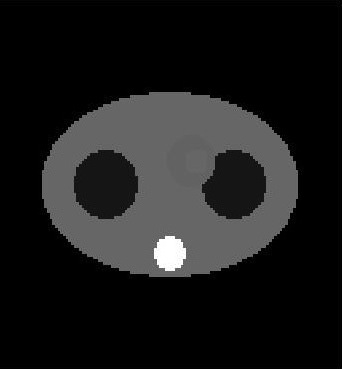
The figures below are the central slices of our objects:
 .
. 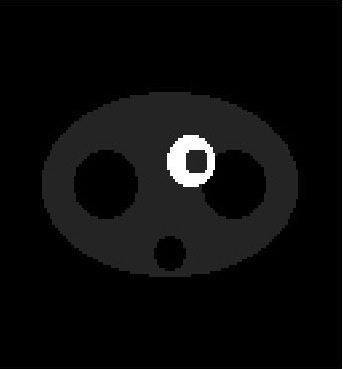
Figure A7.1: The central slices of the the attenuation and activity objects.
The following displays the output from running the PHG for this simulation.
prompt% phg tutor1.phg_param
Command line: phg tutor1.phg_param
Execution of phg occurred on 03 22 1994 (12:34:52 PM) Simulating SPECT.
Stratification is off.
Forced Detection is off.
Forced non-absorption is on.
Acceptance angle is (+/-) 5.0 degrees.
Sine of acceptance angle is 0.087.
Photon energy is 140.5 keV.
Number of decays to simulate = 100000000.
Decay time = 60 seconds.
History file is not being created.
Positron range is not being modeled.
Acollinearity is not being modeled.
Minimum energy threshold is 110.0
Binning is being done.
Debugging is OFF.
Voxel as point source is off.
Random seed is 0.
***************** Simulation Beginning *************
***************** Simulation Finished *************
Real time for calculating time bin decays = 285.9 seconds.
Real time for tracking photons = 81882.1 seconds.
Total CPU time for calculating time bin decays = 12.0 seconds.
Total CPU time for tracking photons = 73759.0. seconds
CPU time for simulation = 73771.0.
PHG Simulation Succeeded!
***************** Processing Binning Data *************
Total photons in history list = 392893.
Total accepted photons = 295942.
Sum of accepted weights = 3.23e+09.
Sum of accepted squared weights = 3.52e+13.
Quality factor = 1.00e+00.
***************** Finished Processing Binning Data *************
Execution of PHG terminated on 03 23 1994 (11:35:56 AM)
prompt%
The following figures illustrate the sinograms and reconstructed images for the primaries and scattered photons. Note that the reconstructed images have not been attenuation corrected. Reconstructions were performed filtered backprojection with a Hann filter.
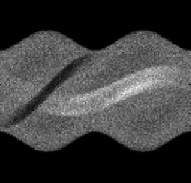
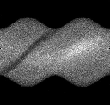
Figure A7.2 - Primary Sinogram and Scatter Sinogram
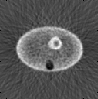
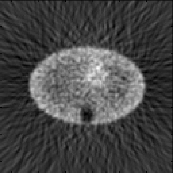
Figure A7.3 - Primary Image and Scatter Image
B. Using MatLab scripts to define block detector parameter files
Contents
Some of the text parameter files used to define tomographs based on block detectors are very large and repetitive. In particular, the ring and block parameter files would be very difficult to type in by hand. We have created some MatLab scripts to subtantially reduce some of the repetitive text entry.
Defining a block parameter file
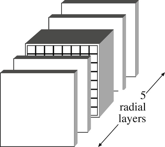
A block detector can be split into layers radially. Each layer can be subdivided into rectangular elements with boundaries parallel to the transaxial and axial faces of the block; these boundaries run through the entire layer, as shown in figure 12 of the block detector section. A text parameter file defines the block dimensions, layer thicknesses, the boundaries within the layers, and the materials for each element. We currently provide two MatLab scripts to help create these files, define_regular_block.m and define_block.m (both text files). define_regular_block.m is simpler to use, but defines only a limited subset of possible blocks: it creates blocks with a regular array of crystals as one layer, and allows one or two solid layers of inactive (e.g., non-scintillating) material in front of and behind the crystal layer to represent crystal wrap and/or detector block housing. The crystal layer can also include crystal wrap and detector block housing (see Figure B1 below). define_block.m allows complete freedom in the block definition, but requires considerably more user input. Both define_regular_block.m and define_block.m use a function called blk_gen.m to write the block parameter file: a user wishing to create a number of blocks with similar characteristics may find it more convenient to write their own MatLab program calling this sub-function.
Figure B1 - Regular block format definable in define_regular_block.m. The blocks can be up to five radial layers, with one or two layers of detector block housing and/or crystal wrap in front of and behind the crystal layer. The crystal layer can also have housing and wrap or other material between the crystals. The crystals have identical dimensions and consist of the same material.
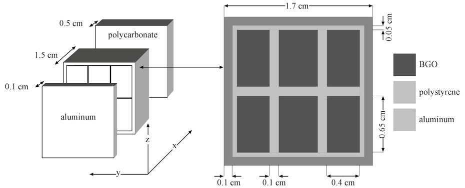
Below we show an example using define_regular_block.m in MatLab to create a block parameter file for the block shown in Figure B2.
Figure B2 - Diagram of block described in example block parameters file. The block is housed in 0.1 cm aluminum front and sides and a 0.5 cm thick slab of polycarbonate is placed on the back to represent a light guide/optical fibers. The detector crystals are 0.4 cm X 0.65 cm X 1.5 cm of BGO. The sides of the detector crystals are wrapped with 0.5 cm polystyrene.
The prompts and other text written by define_regular_block.m are shown in plain text, user responses in bold face.
>> block_input = define_regular_block()
Creating a detector block parameter file for SimSET.
This program creates regular scintillator arrays with
block housing and crystal wrapping as the only additional
options. Another program, define_block.m, allows for more
general arrays. See the website for more info.
Please enter the file name for the block parameters: tutor_B.blkpar
Please enter the following information for the header.
Author name: R Harrison
Enter comment -
terminate with 2 consecutive carriage returns:
Block parameter file for the block shown in Figure B2
of the tutorials on the SimSET website
http://depts.washington.edu/simset/html/user_guide/tutorials.html#figureB2Now define the block geometry and materials.
How many scintillator elements (e.g. crystals) are there
in the transaxial (y) direction: 3
in the axial (z) direction: 2What are the dimensions of these elements in the
in the radial (x) direction (cm): 1.5
in the transaxial (y) direction (cm): 0.4
in the axial (z) direction (cm): 0.65The transaxial and axial sides of the scintillator elements
can have a layer of wrapping.(e.g., paint or tape).Are these elements wrapped? (y/n) [y]:There can be housing material on the transaxial and axial
How thick is the wrap (note this will be doubled between crystals) (cm)? 0.05
sides of the scintillator block.Is there housing material on these sides? (y/n) [y]:
How thick is the housing on the axial and transaxial sides (cm)? 0.1Radially there can be up to two layers of uniform material in front of
and behind the scintillator array (e.g. module housing).How many layers of material are there before the scintillator (0, 1, or 2)? 1
How thick is radial layer 1 (cm)? 0.1How many layers of material are there after the scintillator (0, 1, or 2)? 1
How thick is radial layer 1 (cm)? 0.5Now define the materials used.
Default material indices from phg.data/phg_att_table:
air 0 con_tissue 15 water 1 copper 16 blood 2 perfect_absorber 17 bone 3 LSO 18 brain 4 GSO 19 heart 5 aluminum 20 lung 6 tungsten 21 muscle 7 liver 22 lead 8 fat 23 NaI 9 LaBr3 24 BGO 10 polycarbonateLowVisc 25 iron 11 polyethyleneNEMA 26 graphite 12 polymethylMethacryl 27 tin 13 polystyreneFibers 28 GI_tract 14
When using the default phg_att_table, you can use these material
indices to answer the following. If, however, you are using a
custom table you should use the indices appropriate to that table.
What is the scintillator material: 10
What is the wrap material: 28
What is the housing material on the axial and transaxial sides: 20
What is the material for the first radial layer in front of the scintillator: 20
What is the material for the first radial layer behind the scintillator: 25block_input =
[1x1 struct] [1x1 struct]
>>
This process created the block parameter file tutor_B.blkpar.
For extremely simple blocks, in particular those consisting of only one element, it may be easier to create the block parameter file in a text editor. We give an example of a lead septa parameter file in tutor_B_septa.blkpar for a lead septa 0.2 cm thick and 1.5 cm long. This parameter file and tutor_B.blkpar (the parameter file defined above) are used to create a sample ring parameter file below in the section Example: ring parameter file.
Defining a ring parameter file
A ring parameter file gives an arrangement of detector blocks like those defined above. A ring can have many different types of blocks though all the blocks in the ring must have the same axial extent as the ring (e.g., Figure B3 in the follwoing section).
Ring parameter files, like block parameter files, can be extremely long and repetitive. We currently provide a MatLab script to help create them, define_ring.m (text file). define_ring.m uses a function called ring_gen.m to write the ring parameter file: a user wishing to create a number of rings with similar characteristics may find it more convenient to write their own MatLab program calling this sub-function.
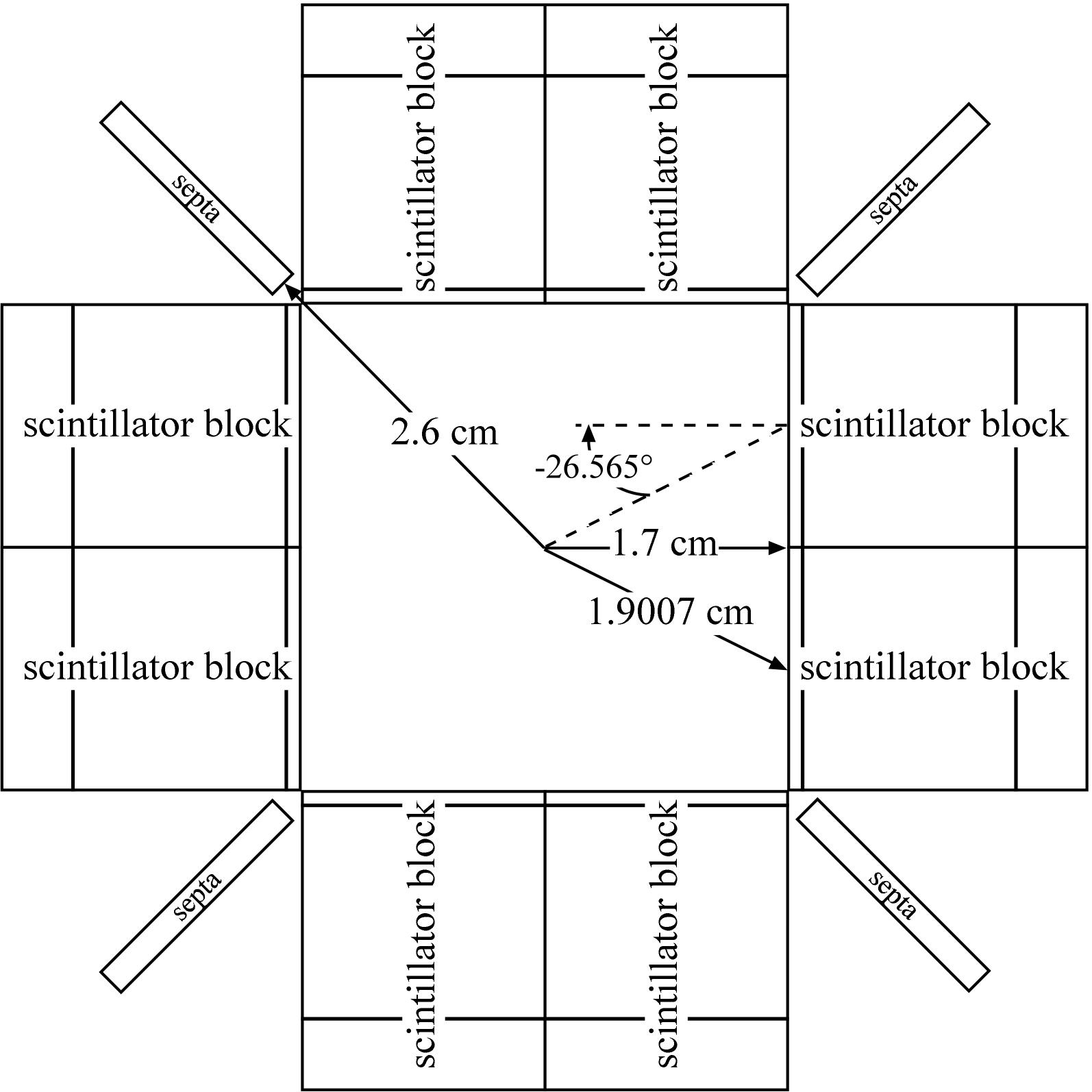
Below we show an example using define_ring.m to create a ring parameter file with the blocks defined above (in Example: block parameter files). The ring we are defining is shown in Figure B3.
Figure B3 - Diagram of ring described in example ring parameters file. Eight scintillator blocks are arranged in a square. The distance from the origin to the tomograph axis of a block (the center of the front face) is 1.9007cm. Adjacent blocks are rotated +/-26.565° (positive angles correspond to counterclockwise rotations from perpendicular to the radius vector). Septa are placed between the paired detector blocks at a radius of 2.6 cm.
The prompts and other text written by define_ring.m are shown in plain text, user responses in bold face .
>> ring_input = define_ring()
Creating a detector ring parameter file for SimSET.
This program fills one ring with block detectors,
prompting the user for the block filenames and positioning
information for each series of blocks.
See the website for more info.Please enter the file name for the ring parameters: tutor_B.rngpar
Please enter the following information for the header.
Author name: R Harrison
Enter comment -
terminate with 2 consecutive carriage returns:
Ring parameter file for the ring shown in Figure B3
of the tutorials on the SimSET website
http://depts.washington.edu/simset/html/user_guide/tutorials.html#figureB3Define the outer bounds of the ring: the minimum and maximum
axial values in the ring; the radius of a cylinder separating
the detectors from the collimator or object (the inner radius of the the
detector system); and the radius of cylinder that lies entirely
outside the detector system (the outer radius, separating the
tomograph from the rest of the universe).Radial extent of ring.
Radius of a cylinder separating the detectors from the collimator (cm): 1.7
Radius of a cylinder separating the detectors from the universe (cm): 4.17Axial extent of ring: this is not the final axial position of the ring.
Multiple copies of the ring can be given different axial shifts in
the detector parameter file.Minimum axial extent of the ring (cm): -.85
Maximum axial extent of the ring (cm): .85Now specify the blocks in the ring. The program will prompt
you for a block parameter file, then ask you how many of
this block type are in the ring and how to place them. This
will be repeated until you have no more blocks you wish to
include in the ring.Enter the data for block type 1
Enter the data for block type 2Enter file name the block parameters: tutor_B.blkpar
Radius at which to place the blocks (cm): 1.9007
Axial position of blocks relative to the ring (cm): 0
How many of this block type? 8Angular position (azimuth) for first block (degrees): 26.565
Are the rest of this block type evenly distributed around the ring? (y/n) [y]: n
Angular position for next block (degrees): 63.435
Angular position for next block (degrees): 116.565
Angular position for next block (degrees): 153.435
Angular position for next block (degrees): 206.565
Angular position for next block (degrees): 243.435
Angular position for next block (degrees): 296.565
Angular position for next block (degrees): -26.565The blocks can be rotated in the transaxial plane. A rotation
of 0 degrees will position the block with its front face tangent
to the cylinder at the radius given above. A poistive value
will rotate the block counterclockwise, a negative value clockwise.Angular tilt for first block (degrees): -26.565
Do the rest of this block type have this same tilt? (y/n) [y]: n
Tilt for next block (degrees): 26.565
Tilt for next block (degrees): -26.565
Tilt for next block (degrees): 26.565
Tilt for next block (degrees): -26.565
Tilt for next block (degrees): 26.565
Tilt for next block (degrees): -26.565
Tilt for next block (degrees): 26.565Add more blocks to the ring? (y/n) [y]: y
Enter file name the block parameters: tutor_B_septa.blkpar
Radius at which to place the blocks (cm): 2.6
Axial position of blocks relative to the ring (cm): 0
How many of this block type? 4Angular position (azimuth) for first block (degrees): 45
Are the rest of this block type evenly distributed around the ring? (y/n) [y]:The blocks can be rotated in the transaxial plane. A rotation
of 0 degrees will position the block with its front face tangent
to the cylinder at the radius given above. A poistive value
will rotate the block counterclockwise, a negative value clockwise.Angular tilt for first block (degrees): 0
Do the rest of this block type have this same tilt? (y/n) [y]:Add more blocks to the ring? (y/n) [y]: n
Ring parameter file generation complete.
ring_input =
[1x1 struct] [1x1 struct] [1x2 struct]
This process created the block parameter file tutor_B.rngpar.
Last revised by: Robert Harrison Revision date: April 26 2011