Summer Interns Report: BlueROV Team: Autonomous Position Tracking With Commercial ROVs
By Ali Jones and Florian Schwarzinger

Introduction and Project Goals
Over the course of this summer, we have been working to turn two commercially available, hobbyist-grade ROVs into platforms for underwater science. Our goal with this project was to evaluate the available hardware and software of the BlueRobotics BlueROV2 and determine the viability of this transformation. The technical component of this goal was to use OpenCV and the Robotic Operating System (ROS) in programming one ROV to autonomously follow the other.
Technical Details
First Build
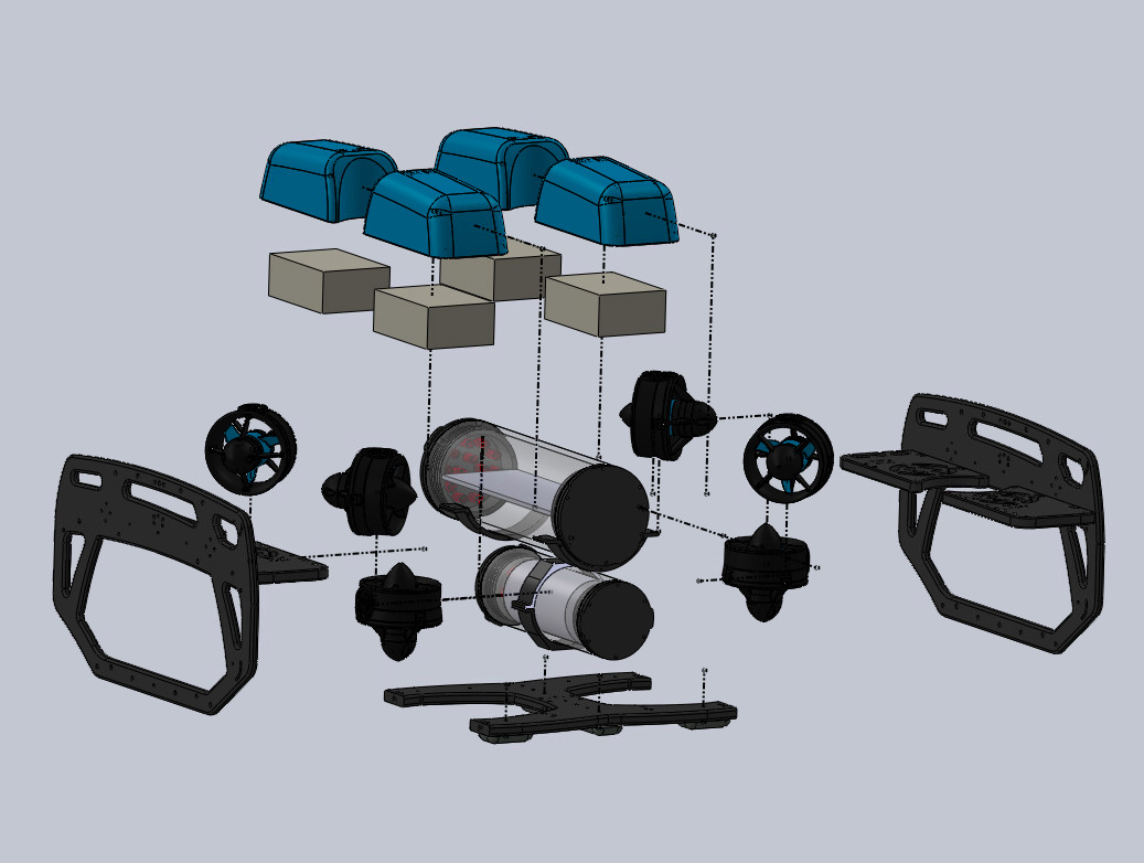
The first step in analyzing and modifying the BlueROV2s was, of course, building the BlueROV2s. Following the build instructions provided by BlueRobotics, we were able to build and connect to the first vehicle in a day. The basic kit includes six thrusters with electronic speed controllers (ESCs) activated by a Pixhawk flight controller and a Raspberry Pi companion computer. The electronics are housed in a cylindrical tube, and cables are waterproofed with penetrators through an aluminum end-cap. The ROV also comes equipped with an on-board battery, lights, and a low-light USB camera on a servo. Data and thruster commands are sent from the topside computer over an Ethernet tether. An exploded view of the ROV can be seen in figure 2.
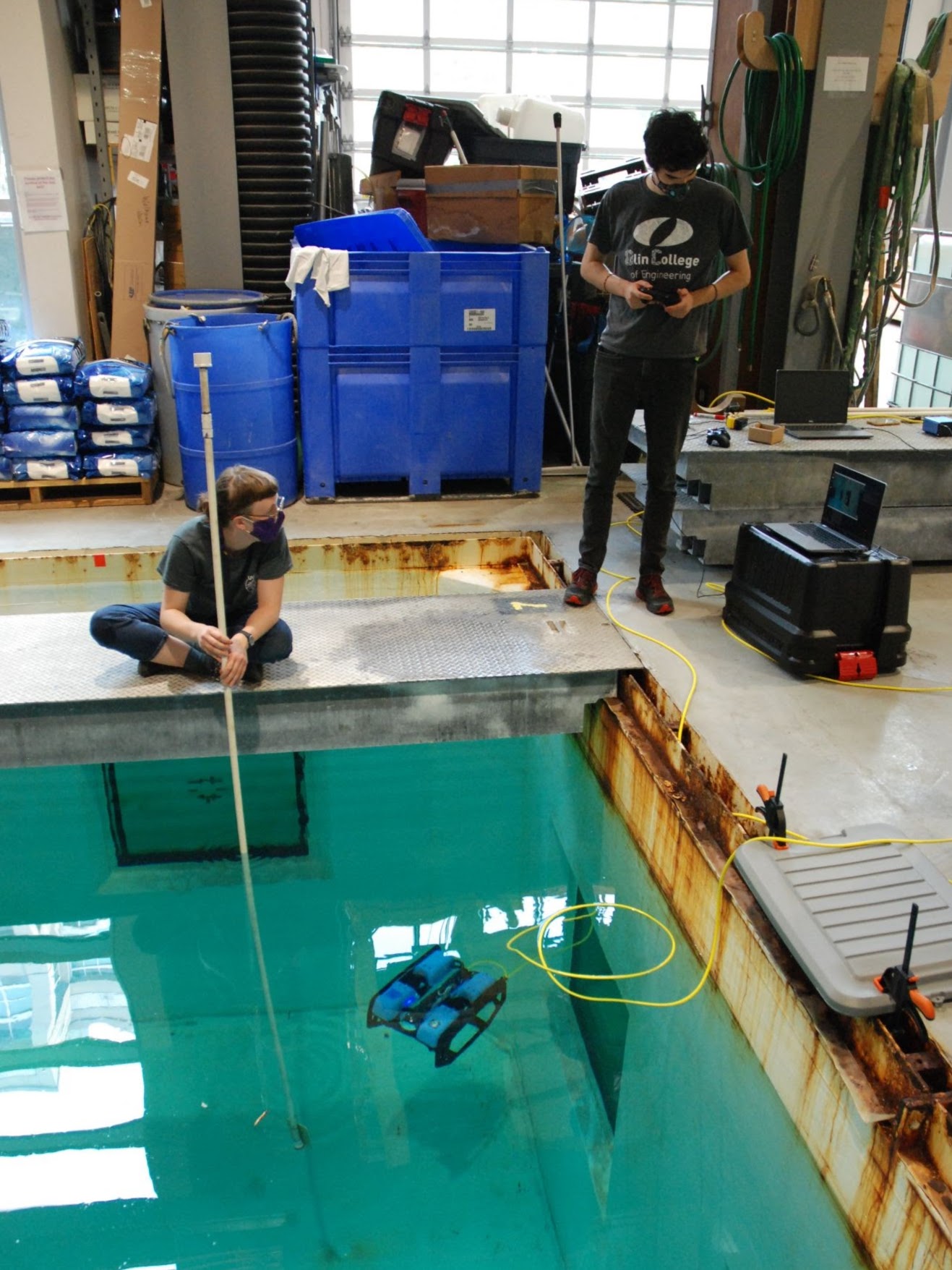
Once we built the ROV and confirmed we could control the thrusters in air, we were ready for our first tank test. After pre-dive checks, we launched the vehicle. We piloted the ROV with a standard gamepad controller and had responsive control over five degrees of freedom: X, Y, Z, yaw, and roll. The BlueROV2s are small and maneuverable while still stable and easy to control.
Vehicle Software Architecture
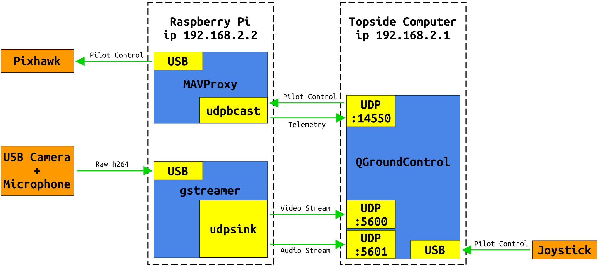
Before any of our modifications, the ROV communicated with the topside computer as seen in figure 3. Out of the box, the BlueROV2s run through a program called QGroundControl (QGC). QGC is a framework built around MAVLink, a lightweight messaging system used to communicate with drones. We worked to eliminate QGC, but at first we used it to calibrate on-board sensors and motors, control the vehicle manually, and see the video stream. Joystick input was processed by QGC and sent as a MAVLink message to the Pixhawk, the on-board flight controller. Audio, video, and telemetry (such as battery voltage, armed or disarmed status, etc) were passed from the onboard computer to QGC and displayed.
In order to integrate autonomous control into the ROVs, we needed to bypass QGC. We used a package created by an engineer at BlueRobotics as a template, and ended up breaking several QGC functions into separate ROS nodes. The nodes transfer information to and from the ROV by publishing or subscribing to ROS topics. Our final software diagram can be seen in figure 4. The Raspberry Pi architecture remains mostly untouched, but the topside computer architecture now shows the publish-subscribe system. Purple arrows denote ROS topics; the head indicates nodes are subscribing to certain topics, and the tail indicates nodes are publishing messages across the topics.
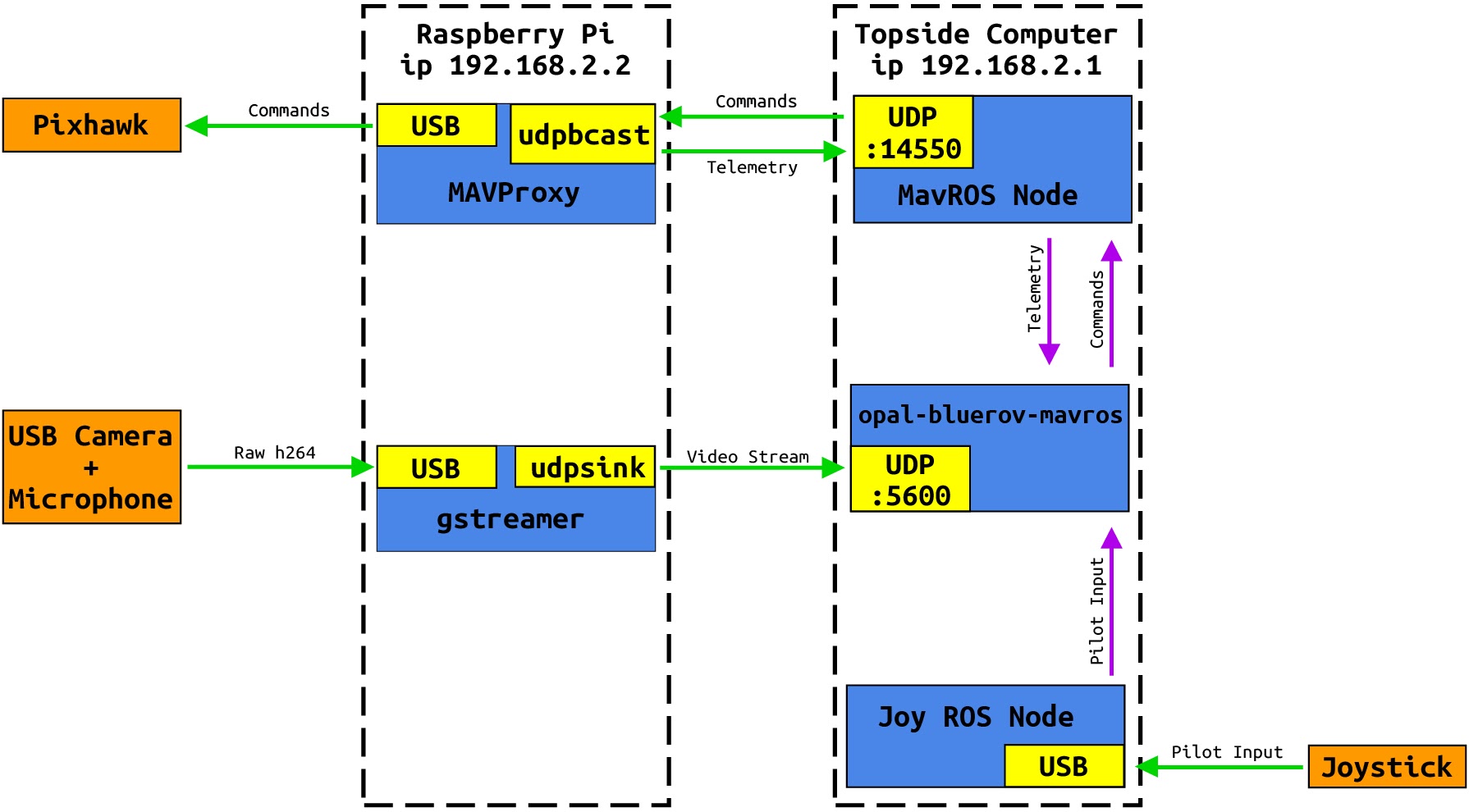
The three topside computer nodes work together to send messages to and receive data from the ROV. The Joy ROS Node reads axes and button values from a connected joystick and publishes them to the /joy ROS topic. This information is then read by the Opal-BlueROV-mavros Node, which processes the input and sends instructions to the MavROS Node. The MavROS Node turns the ROS messages into MavLink messages, which can be read and processed by the ROV. This communication also works in reverse, allowing the Opal-BlueROV-mavros Node to read telemetry data and other messages from the ROV.
Autonomous ROV Control
It took us significant trial and error and many small milestones to converge on the above software. After we built the ROVs, we began looking into automation. To familiarize ourselves with the programs necessary to communicate with the ROVs, we created a mini-project using the built-in ROS turtle simulation. The turtle simulation uses two nodes and a handful of topics to allow the user to control a turtle sprite with keyboard input. Our goal was to write our own nodes to instead control the turtle sprite with OpenCV and an ArUco tag. We each succeeded in moving the turtle in different ways, first with the computer webcam and then with the camera on the ROV.
From the turtle sprites, we moved on to integrating ROS with the BlueROV2s. The first step in this direction was figuring out how to send MavLink messages to the ROV. First we used MavProxy, a command line based ground station able to handle these messages. We were able to connect to the ROV, arm and disarm the motors, and spin the thrusters using various commands. MavProxy is limited by what you can send through the command line, however, so we then moved on to direct control through Python scripts. We first tried Pymavlink, a Python library that processes MavLink messages. We successfully created a script that armed the ROV, spun the thrusters for a set time, and disarmed.
Without ROS, however, connecting all of the various actuators and sensors on the BlueROV2s would have been a significant challenge. Therefore, we moved away from MavProxy and Pymavlink and began looking into the MavROS node. MavROS is able to interface directly with MavLink messages, so can easily send commands to the ROV. Looking further into MavROS, we found the BlueROV-ROS-Playground package made by a BlueRobotics Engineer. It included scripts for basic video streaming and manual control of the ROV, and gave us a stepping off point to begin integrating ArUco detection and autonomous control.
Using the Playground as a template, we created the Opal-BlueRov-MavROS package. We began by building in more complete joystick control, including arming and disarming, activating lights, and controlling the camera. These functions all used different MavROS messages and services to communicate with the onboard Raspberry Pi and Pixhawk. Next, we created a script that uses OpenCV to detect the center point of an ArUco fiducial marker. Finally, we built different modes for manual and autonomous control, and mapped the detected ArUco tag position to thruster commands.
We began by linearly mapping only two dimensions with lateral left/right and ascend/descend commands. After testing the ROV behavior to better tune the response and work out bugs, we calibrated the on-board camera to allow OpenCV to accurately detect the 3D position and orientation of the tag. From there we were able to add distance and yaw control. The final result is an ROV that can detect the position of an ArUco tag and respond autonomously with four degrees of control: lateral left/right, yaw left/right, ascend/descend, and forward/back.
Stereo Camera Integration
In parallel with autonomous control, we modified one of the ROVs to accommodate an external sensor, the Numurus 3DX-C stereo camera. Proof that a sensor can be integrated is critical in determining the viability of the BlueROV2s for future science, and a stereo camera in particular is useful because it provides accurate depth readings.
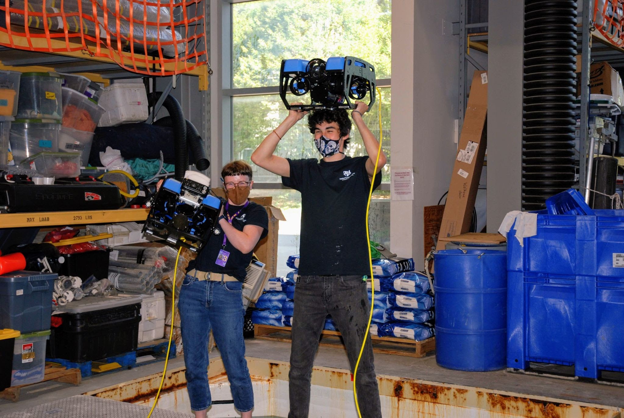
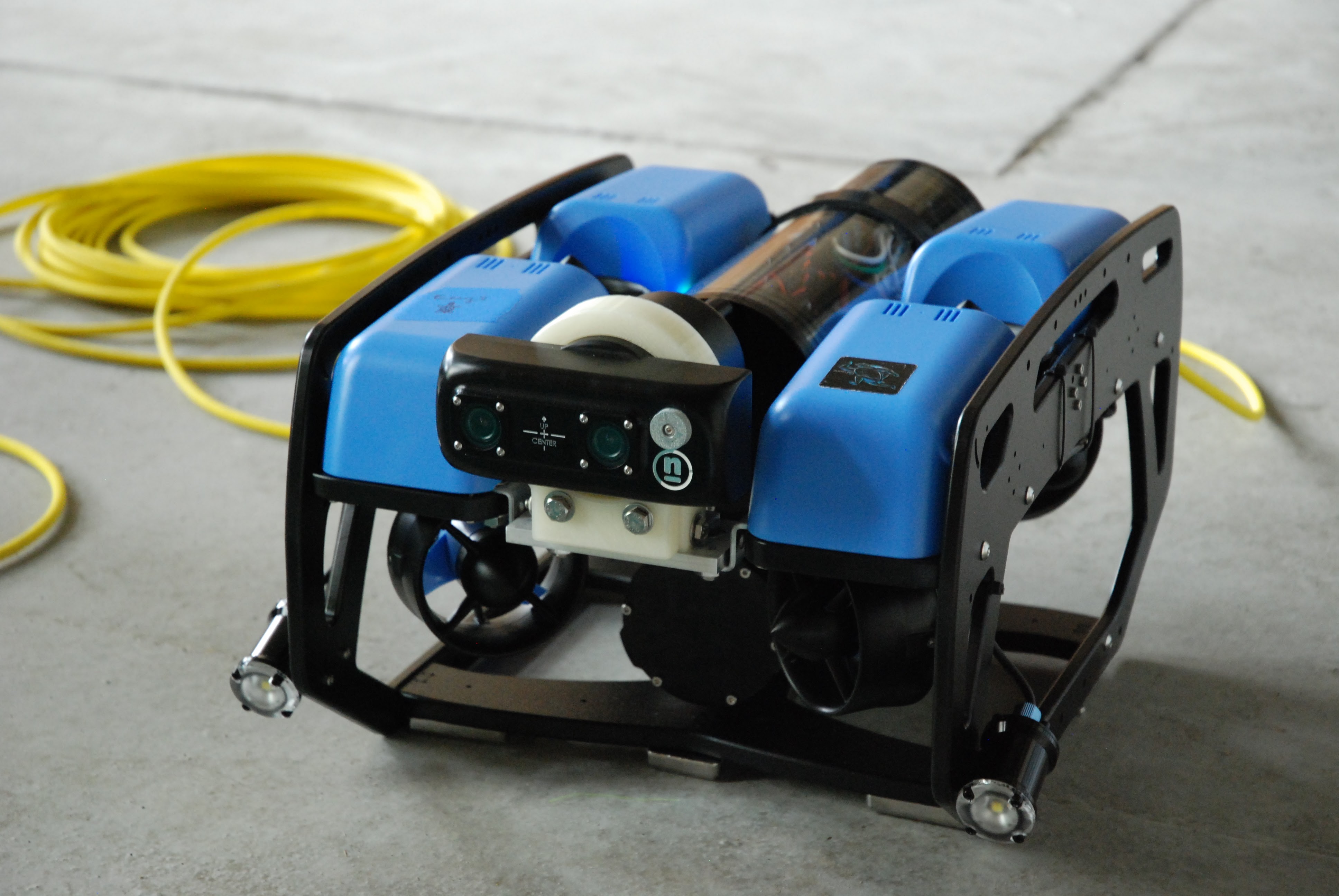
There isn’t much room to mount with the basic BlueROV2 configuration. There are a few add-ons (namely the BlueROV Heavy and the Payload Skid) that provide more mounting locations, but neither have a great place to accommodate for the camera field of view. Therefore, to both protect the sensor head and streamline the design we removed the existing camera, shifted the electronics enclosure back, and nestled the Numurus in the front. The sensor is held in place with a 3D printed mount bracketed to a custom aluminum platform we machined. The ROV with the Numurus mounted can be seen in figure 6.
The next challenge to integrate the Numurus was waterproofing. The cable was too large to fit through the standard BlueRobotics penetrators, so this required us to both design our own scaled-up penetrator and remake the end cap to accommodate the larger size. The penetrator was machined in the APL shop, and we machined the end cap in the MEB annex. Once manufacturing was complete, we were able to pot the cable in the penetrator and assemble. The new assembly held a vacuum on the first try.
Finally, we had to electrically connect the Numurus to both data processing and power. To achieve the former, we soldered the end of an Ethernet cable to the Numurus cable and plugged it into the Raspberry Pi with an Ethernet-USB converter. Power was easier; we were able to run the power cables directly into the BlueROV2 power terminal and use power from the on-board battery. This power block has several more open screw terminals, so it could accommodate even more sensors if needed. Finally, we set up a network bridge to allow the topside computer to connect to both the ROV and the Numurus simultaneously. After this integration, we were able to pilot the ROV and see the Numurus video stream.
Results
At the end of the summer, we successfully proved that autonomous following with the BlueROV2s is possible. We began with simple, 2D autonomous control, directing the ROV with an ArUco tag on a stick. From here we built in responses for distance and yaw, giving the ROV four degrees of control. The control is relatively simple; as the tag moves away from the center of the camera frame, the ROV responds by increasing thruster RPM in whatever axes necessary to recenter it.
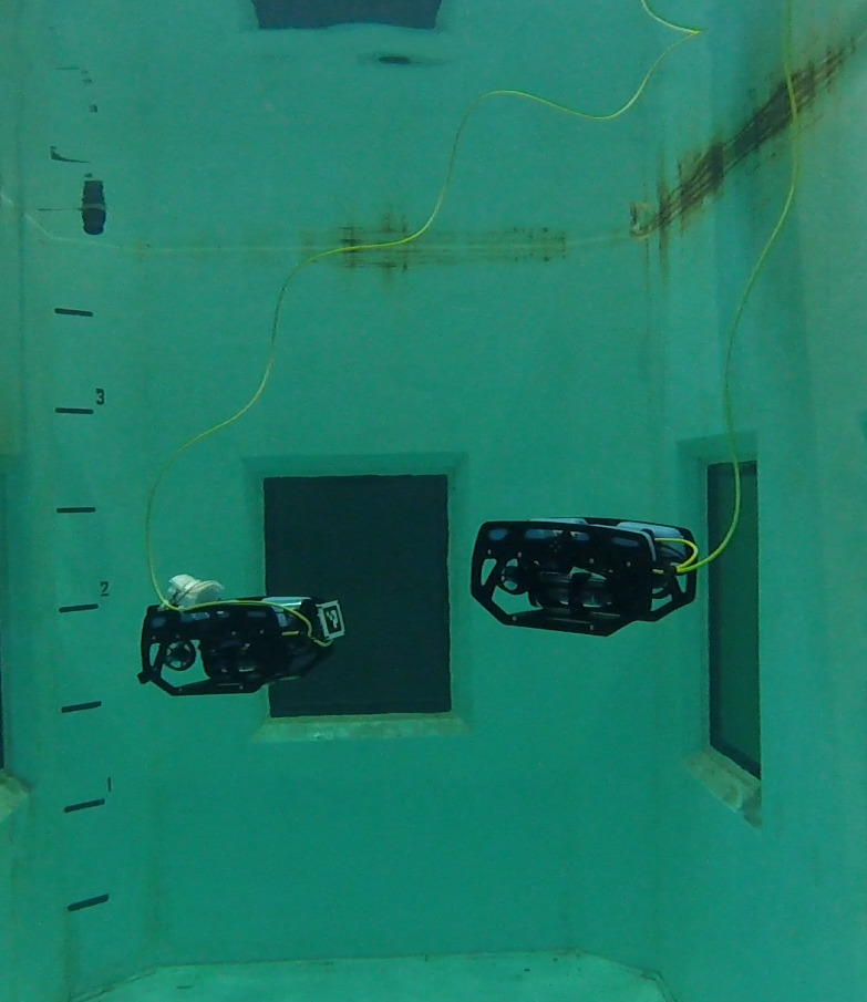
Finally, we tested this control by attaching a tag to the back of one ROV and setting the other to follow. The following was not without its quirks: the control is strictly linear and has no feedback loops, the yaw response can overshoot and cause the follower to lose sight of the leader, and the ArUco marker must remain perfectly unobstructed and clear. Overall, however, the follower ROV was able to remain centered behind the leader as it drove around the tank for minutes at a time.
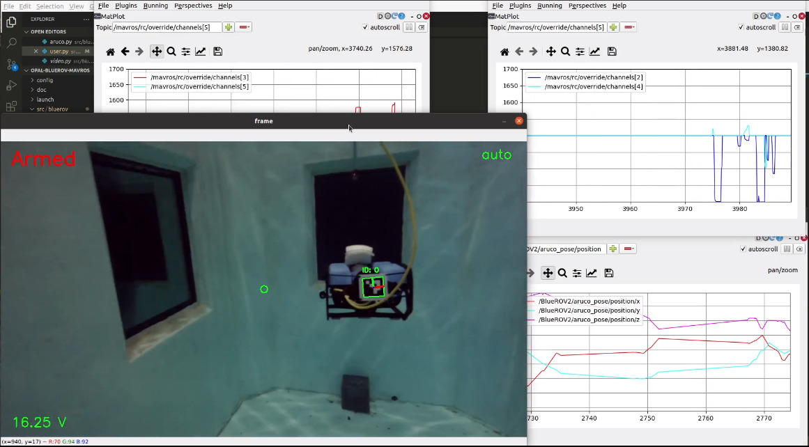
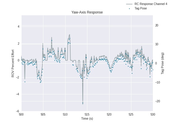
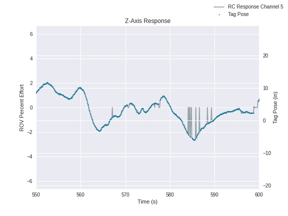
Plots of the response versus time can be seen in figure 7. The left axis shows the thruster response of the ROV, and the right axis shows the detected tag pose. The yaw axis response (left) is fairly accurate, though fewer instances of the tag were detected than in the z-axis response (right). This indicates that the following is limited by the accuracy of the detection and the camera quality.
Conclusions and Next Steps
As with any instrument, the BlueROV2 has both advantages and disadvantages in its application as a science platform. The most significant are listed in the tables below. Overall, the BlueROV2 has displayed definite potential for future modifications and usage.
Disadvantages
- Can’t control individual thrusters, only channels (i.e currently no pitch control)
- Limited mounting space
- Lightweight, so heavy add-ons can disturb balance
Advantages
- Autonomous position tracking is possible
- Can interpret several different mavros messages for control
- On-board battery and Raspberry Pi – tetherless automation theoretically possible
- Small and maneuverable
- External sensor integration is feasible
There are likely two niches that the BlueROV2s could fill. The first is to use one ROV to increase the control of an external sensor. Often a sensor will be rigid, limiting its field of view. Instead, it could be mounted to the ROV and easily connected to power and data in much the same way as the Numurus. This would allow the user to manually move the sensor or autonomously park it with a stationary ArUco tag.
In addition to increased sensor control with a single vehicle, the BlueROV2 is small and inexpensive enough to make multi-ROV coordination a possibility. The on-board battery and Raspberry Pi computer could make tetherless automation possible, a necessary first step that prevents tether entanglement underwater. Then, using multiple ArUco tags spaced around a tank, the ROV could determine its location and respond accordingly.
Whatever the future of the BlueROV2s, we hope that our work this summer has demonstrated their potential for autonomous control and modifications in the name of underwater science.
Photos