
| Home |
| 3-D Echo |
| 3-D MRI |
| Applications |
| Quantitative Angiography |
| Centerline™ |
| Visual Guidance |
| Personnel |
| Publications |
| Contact Us |
Image Border Analysis
The images are reviewed and those corresponding to end diastole and end systole are manually selected, using custom software running on a graphics workstation. End diastole is assigned to the frame meeting two or more of these criteria, in order of weight: The largest LV cavity size; the last frame before mitral closure begins; or the last frame before R-wave onset. Because some delay occurs between ECG signal and image transmission, slight asynchrony may require visual assessment of frames for the "closest" ED.
End systole is assigned to the frame meeting two or more of the following criteria, in order of weight: The smallest chamber size; in frames traversing the aortic valve, the first frame after aortic closure begins; or the last frame before mitral opening begins.
Because of asynchrony in wall motion, the interval from end diastole to end systole is determined for each full cardiac cycle, and then the median interval is applied to all imaging planes.
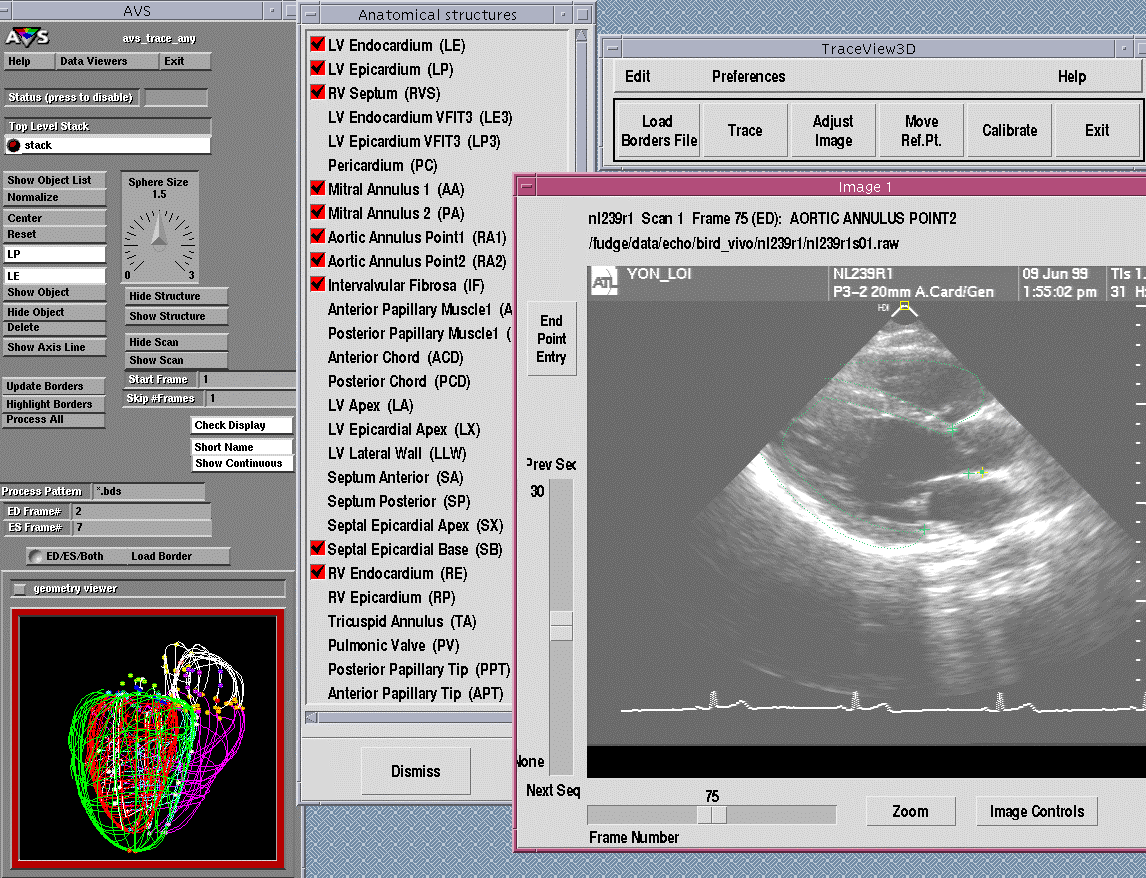 |
| The tracing environment. Users select images from a list, trace structures of interest with unique markers for each structure, and review the results in a fully 3D-registered geometry display (AVSTM), at lower left. The resulting markers and borders are saved to a file with the probe position and timing data for the corresponding raw image. |
The borders of the LV and anatomic features of interest are then manually traced in the selected images. The border points are fitted with a spline curve, and then converted to x, y, z-coordinates using probe position and orientation data. As each border is traced it can be reviewed immediately in 3D in combination with previously traced borders, using a software interface (Advanced Visual Systems, Waltham, MA). This 3D visualization facilitates verification of image plane registration and border tracing consistency. All images are traced using the leading-edge technique, with the border passing midway between the external and internal boundaries of echogenic signals e.g. from the pericardium, endocardium, and leaflet tissue. An example of the tracing environment is shown above.
Back to Top