![[UW Pediatrics]](/bicg/images/uwp24.jpg)
SLIMMER
C. Initializing SLIMMER workspace
When RView finish loading stacks into viewer panels, the stacks will be displayed in the RView panels and SLIMMER tool window will pop up. The left most column of the RView window is reserved for the reference image, although initially it will display arbitrary anatomy in the first stack. The rest of the columns will display the stack images, which are loaded in the order of the stack acquisition time.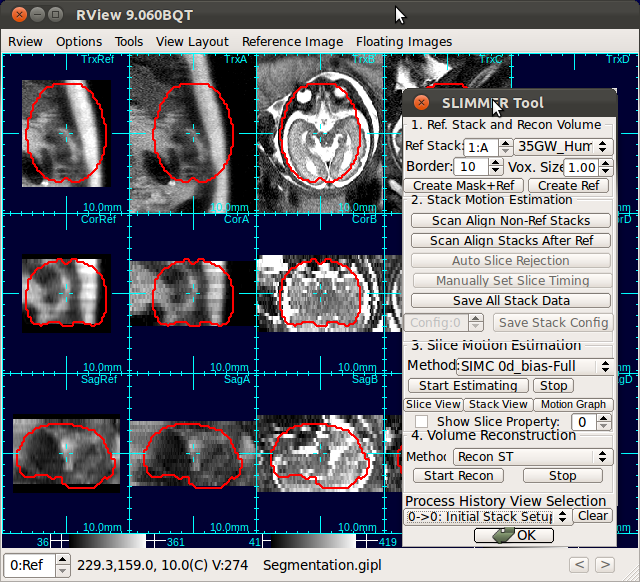
The first step of stack alignment is to generate a reference image from one of the stacks.
1. Generating a reference image
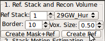
SLIMMER needs a reference image, which can be created from one of the stacks that are loaded. You need to center and reorient the stack before you can use the stack to generate the reference. This reference image will serve as a guideline throughout the motion estimation and volume reconstruction processes. The final reconstruction will be an image that resembles the reference image in terms of the shape and orientation, but with a higher geometrical integrity and a better spatial definition.A stack with the best quality, usually in axial orientation, is recommended for the reference stack. Input the stack index into Ref Stack box of the SLIMMER tool window. Use a numerical index instead of alphabet (A→1, B→2, etc.)
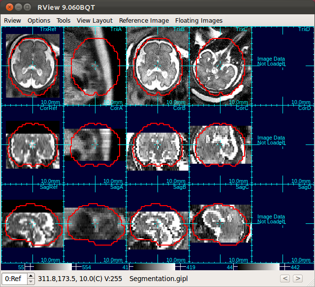
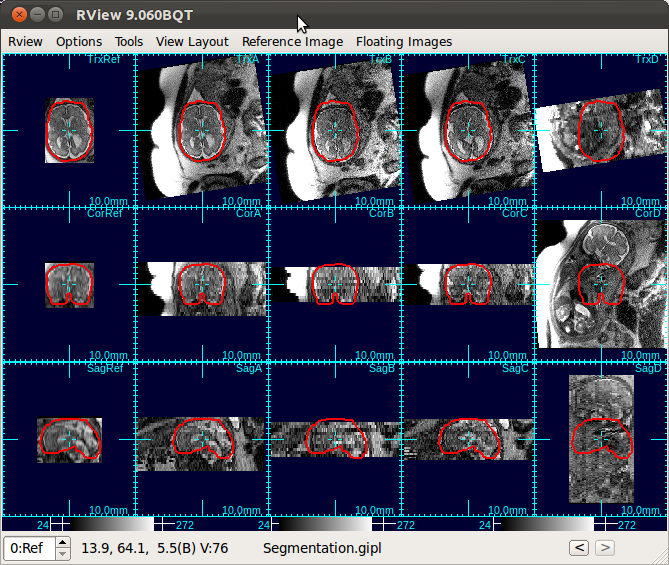
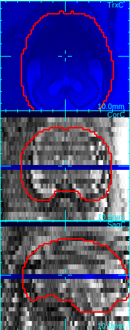
The figure below is an example screen of RView when SLIMMER finished loading DICOM files. In the top-right corner of each panel is a string indicating the view plane and the image name. The left-most column is the reference image (Ref), and is followed by columns of the stack images, alphabetically indexed. In this screen, the stack B (the third column) has all of the three view planes, namely, axial (Trx), coronal (Cor), and sagittal (Sag), correctly oriented, except that the head is upside down.
Input your choice in the Ref Stack box of the SLIMMER tool window.
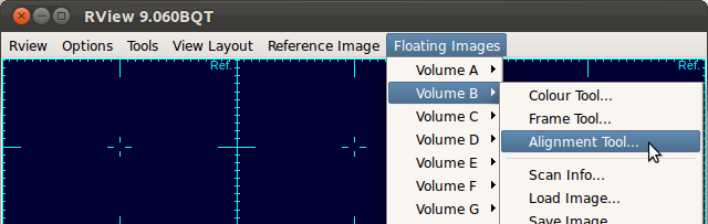
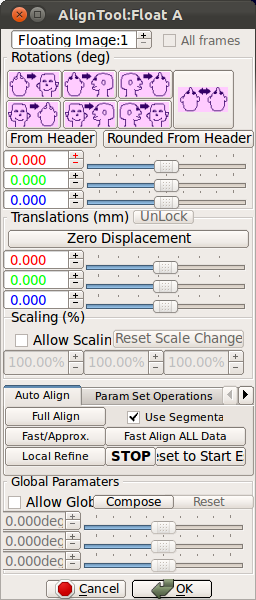
In case you need to recenter or reorient the stack chosen for reference, open the alignment tool for that stack by selecting Floating Images→Volume Index→Alignment Tool...
You can center a stack (use O-key on the keyboard) and adjust the orientation (use Rotation slide bars in the alignment tool), so that the first, second and third view panels of each column display axial, coronal and sagittal views of the brain, respectively. A detailed documentation on the alignment tool is included in RView help.
- O-key on the keyboard: Recenters the stack under the mouse cursor.
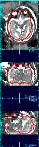
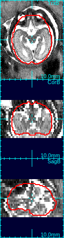
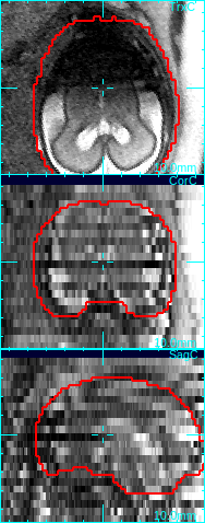
In the figure below, the first column shows that brain is off-centered, and upside-down. Move the mouse cursor to the center of the anatomy, and press o-key once (only once!), and the stack will be recentered so that the current cursor location will be the new center (second column in the figure below).
- Rotation slide bars: Adjusts the orientation of a stack.
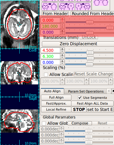
Using the rotation slide bars, correct for the upside-down configuration---in this case, the image needs to be rotated by 180 degrees around the y-axis (the third column, pink box). Often times, the rotation might be complicated involving rotations around all axes. Use the rotation slide bars interactively to find the correct rotation angles.
 |
→ |  |
→ |  |
→ |  |
| Move cursor to the center of anatomy | Press o-key to recenter the stack | Use rotation slide bars to correct rotation | Recreate a mask with a correct size |
2. Selecting the mask
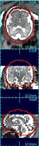
Select the best matching mask type using the mask type list in order to determine the size and shape of the reference mask. The options include the human fetal brains of various gestational age, the human adult brain, and the monkey brains. An ideal mask should include rigid tissues (brain and skull) as much as possible, and exclude maternal tissues and amniotic fluid. For example, the column 4 in the figure above demonstrates a good choice of mask size---it includes the whole brain and skull areas, and the maternal tissues/amniotic fluid regions are almost completely excluded from the mask area.Clicking Create Mask+Ref button will create a reference image from the selected original stack by interpolating it to the resolution specified in Vox. Size box. The contour of the age specific mask will be overlaid in view panels.
3. Aligning stacks to the reference image
(1) Align to the reference using the scanner coordinates
Use Scan Align Non-Ref Stacks button to align non-reference stacks to the reference. This will bring the non-reference stacks to the same position as the reference stack.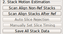
 |
→ | 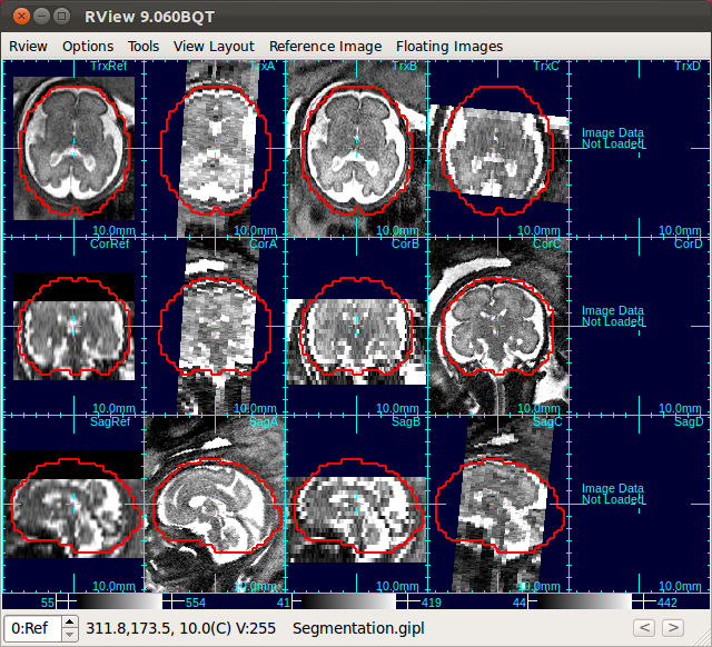 |
| Only Stack 2 is aligned | Click Scan Align Non-Ref Stacks |
 |
| A: Subcutaneous fat, B: bladder |
* Note: Scan Align Non-Ref Stacks automatically detects gimbal-locked stacks and corrects them.
(2) Auto-align to the reference image
In order to compensate for slight fetal motion between the reference stack and non-reference stacks, RView provides a tool for an automatic stack-to-stack alignment. If the initial stack configuration is closely aligned to the reference, use Local Refine alignment button. This button alignes the floating image in Floating Image: field to the reference image, by correcting for the gross motion of the head in the floating image with respect to the head in the reference image.Repeat this for all non-ref stacks for the best slice motion estimate.
If the auto alignment fails for any reason, click Reset to Start Estimate to revert the previous alignment state, and try manual alignment.
4. (Optional) Manually aligning stacks to the reference image
User can maually align a stack to the reference using the alignment tool. Use O-key on the keyboard to modify translational motion, and Rotation slide bars for rotational motion. Make sure that all three views in the axial, sagittal and coronal planes are approximately aligned with the reference image. A detailed documentation on the alignment tool is included in RView help. Once the stack is manually aligned to the reference image, user can try Local refine button to automatically refine the alignment. If the automatic local refine fails, use Reset to Start Estimate to revert to the previous alignment stage.* Note: When it is difficult to align all stacks to a single reference stack, for example, the fetal motion between stack acquisitions is severe, Scan Align Stacks After Ref button in the Stack Motion Estimation box is particularly useful. Use Scan Align Stacks After Ref button to progressively align stacks.
5. Checklist
Before proceeding, check following items:- Alignment: Use the alignment tool if there remains unresolved misalignment of stacks due to any abrupt motion between stack acquisitions or other reasons.
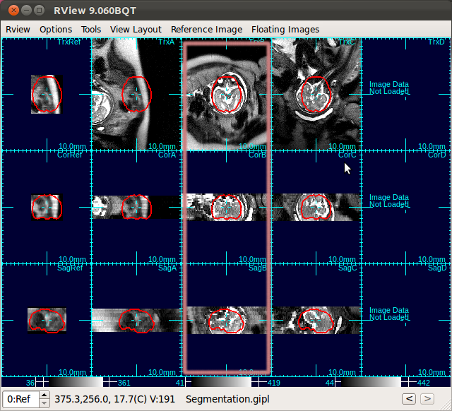
For example, in the below figure, the relative/ position of the fetus to the scanner have changed due to fetal and maternal motion, between the acquisitions of the stack C and the stack D (the fourth and fifth columns). In such a case, use the alignment tool to bring the stack D to the reference fetal brain coordinates.
- Gimbal lock: If a stack is gimbal-locked, click UnLock button in the alignment tool window to resolve it.
RView uses Euler angles to represent rotation. In this representation, rotation may suffer gimbal lock when the y-rotation becomes close to ±90 degrees. If this happens, Unlock button becomes activated. Click this button, and RView will rotate the stack to the gimbal unlocked position and modify Euler angles accordingly.
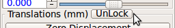
Make sure Unlock button is disabled for all stacks, before proceeding to the next step.
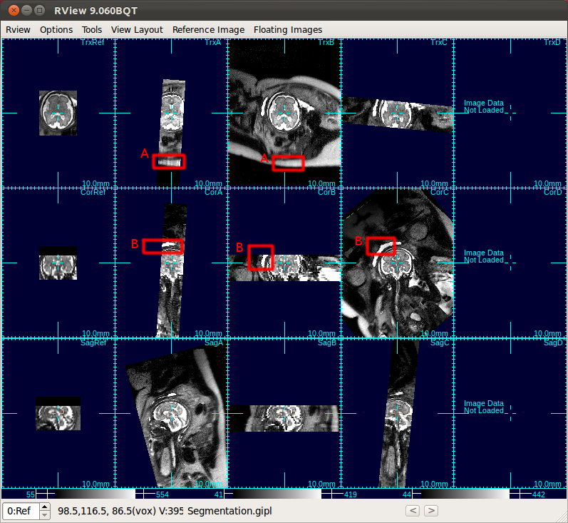
Note: Since Scanner Align Non-Ref Stacks button automatically detects gimbal-lock and unlocks it, use of Unlock button will be necessary only in limited circumstances. - Slice quality: If any slice is blurry, blank, or has any quality issue, move mouse cursor to the slice and press q-key on the keyboard. This will set the quality value of the slice to 0, and the slice will be colored in blue.
The low quality slices will be excluded from motion correction and volume reconstruction. For example, in the figure below, the axial slice is corrupted due to the fetal motion during the slice acquisition. Since the dark area does not reflect the actual anatomy, the image is not consistent with other intersecting images, and thus should be excluded from the motion correction step and the reconstruction step. Simply move the mouse cursor over the corrupted slice in any of the view oritation panels (axial, sagittal or coronal), and click q-key, and the slice quality value will be set to 0.
→ 
Move mouse cursor to a degraded slice. Press q-key to mark a low quality slice.
6. Saving the data
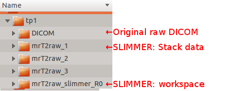
So far, you have loaded DICOM data, and initialized the dataset IN MEMORY only. Nothing is saved until you click Save All Stack Data button in Stack Motion Estimation box of SLIMMER tool window.Clicking this button will open a directory selection window. Select the parent director of the DICOM directory, which will create SLIMMER directories in parallel with the DICOM directory. SLIMMER will generate a stack data directory for each stack (mrT2raw_n) and, and a SLIMMER workspace directory (mrT2raw_slimmer_R0).
Below figure shows an example directory structure. User selected tp1, and SLIMMER directories were created in parallel with the DICOM directory.
Each stack data directory includes following files:
| File name | Description |
| mrT2raw.gipl | Stack image data file |
| ref2mrT2raw.dof | Reference-to-Stack Rigid transformation file |
| ref2mrT2raw.sdof | Stack-to-Slice Rigid transformation file (motion uncorrected) |
| mrT2raw_scanTrans.dof | Scanner-to-Stack Rigid transformation file |
| mrT2raw_DICOMinfo.xml | |
| mrT2raw_GEOMinfo.xml | |
| mrT2raw_MRIinfo.xml |
The SLIMMER workspace directory includes following files:
Note: Drag-and-drop reconConfig.rvw into the RView window to reload the complete SLIMMER state.
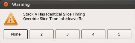
Note: When Save All Stack Data button is pressed, RView automatically check for the correctness of slice timing data of each stack, because the slice timing data provides correlation information between slice motion parameters. If a timing data corruption is detected, Manually Set Slice Timing button becomes activated. Then, user can click this button to manually reset the slice timing by choosing the actual interleaving factor.
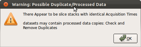
Note: When Save All Stack Data button is pressed, RView automatically checks if any loaded stacks have identical timing data. If identical timing data are detected, a warning window will pop up as below. Make sure to remove any redundant or before-processing stacks before proceeding.
«Tutorial Main ‹prev next›
© 2024 Biomedical Image Computing Group, Division of Neonatology
Department of Pediatrics, University of Washington. All rights reserved.
Privacy |
Terms | Contact Us