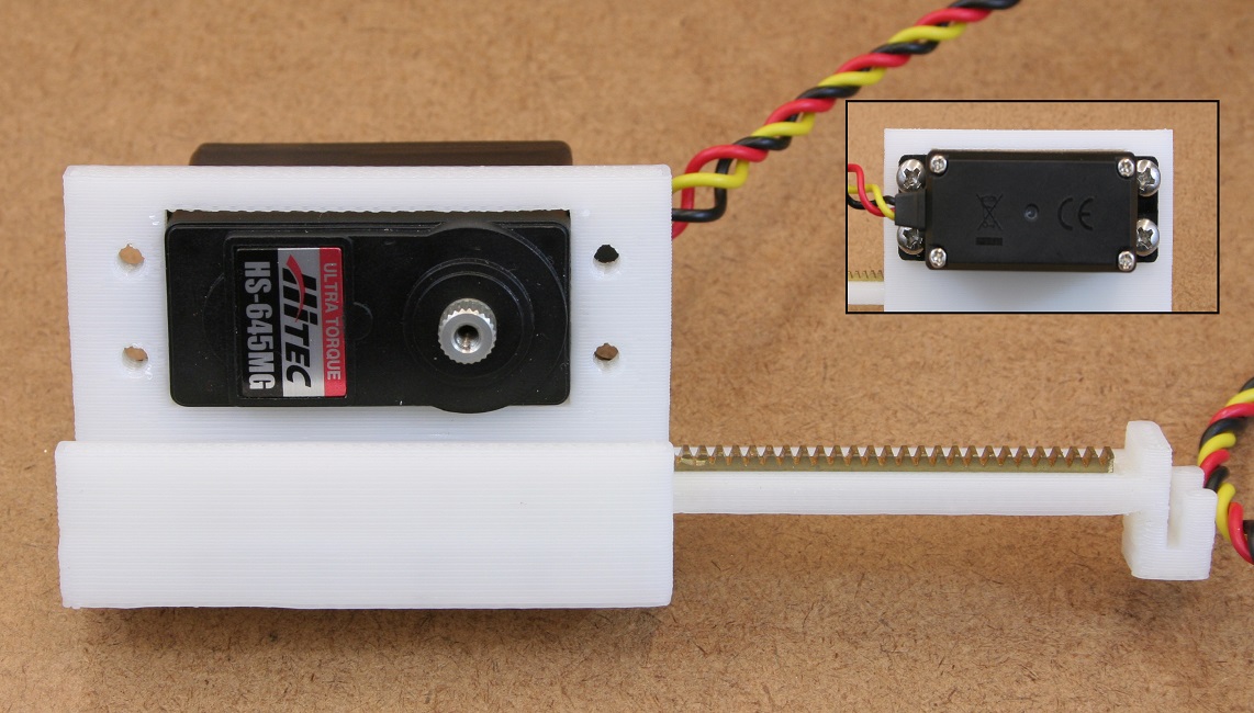
To control addition of media from the sterile media carboy to each of the individual chambers in a highly controlled and yet inexpensive fashion we have developed our own servo-based and 3D-printed syringe pumps.
Technical Note: Although these pumps should be road-tested by users we find that they robustly transfer 1.6ul per pump unit movement on average and are consistent beteween 5(minimum) and 1000(maximum) pump unit movements for a given transfer. As such you can transfer as little of 8ul and as much as 1.6ml in a given transfer event. If higher control of dilution rate is desired commercial syringe pumps may be used in place of homemade pumps however description of how to do so will not be described here for the time being.
photo here
exploded diagram here
3d Prited Parts
"put photo of just the 3d-printed tube holder here"
Alibre/Geomagic and STL files can be found on github or through the
direct link
Laser Cut (or hand made) Parts
The mounting surface may be laser cut or drilled. Mount dimensions are as shown below:
The 12x12in mounting plate used here is in the mount/ directory in the hardware repository on github
Electronics
HS-645MG standard servo (see parts spread sheet).
Purchased Parts
- 48 tooth 48pitch servo mount gear
- 48 pitch gear rack
Assembly
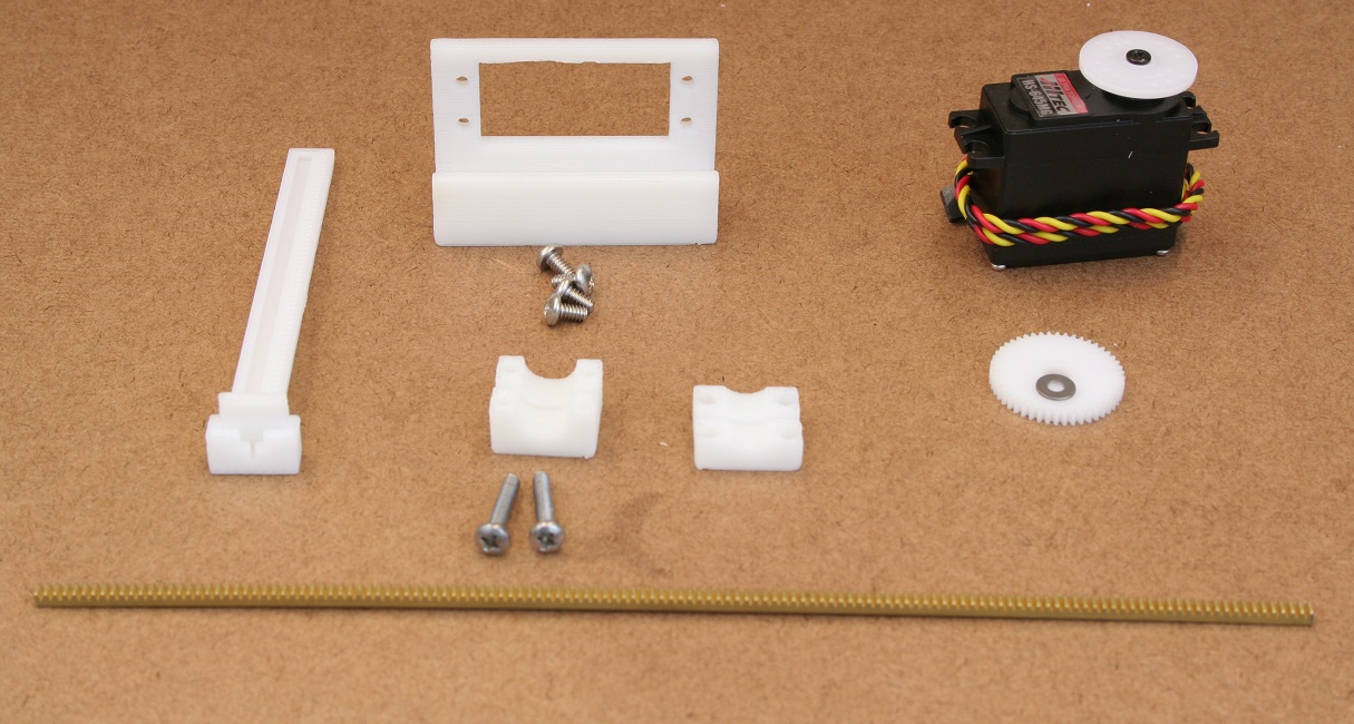
| Gather all 3d printed parts:
- Slide
- Pump body
- Syringe holder top and bottom
Gather all chamber electronics and hardware:
- Servo motor
- Gear
- brass rack
- 4x 1/4" 6-32 machine screws (or M3.5)
- 2x 1/2" 6-32 machine screws (or M3.5)
- 4x 3/8" 6-32 machine screws (or M3.5) (not pictured)
Note: If you do not have a 3d printer there are services that will do the printing for you.
|
|---|
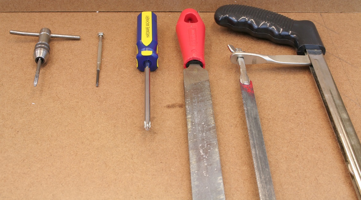
| Gather all tools needed for assembly:
- 6-32 tap (or appropriate metric tap if you're using metric screws)
- #0 screwdriver
- #2 screwdriver
- file or coarse sand paper
- hack saw
- Diagonal cutting pliers or wire cutters (not pictured)
|
|---|
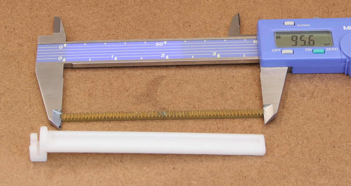
| Cut rack to size
Cut the gear rack to 95mm in length with the hack saw. Once cut to size use the file or sand paper to smooth out the ends. The file can also be used to shorten the length of the rack as needed for fitment.
|
|---|
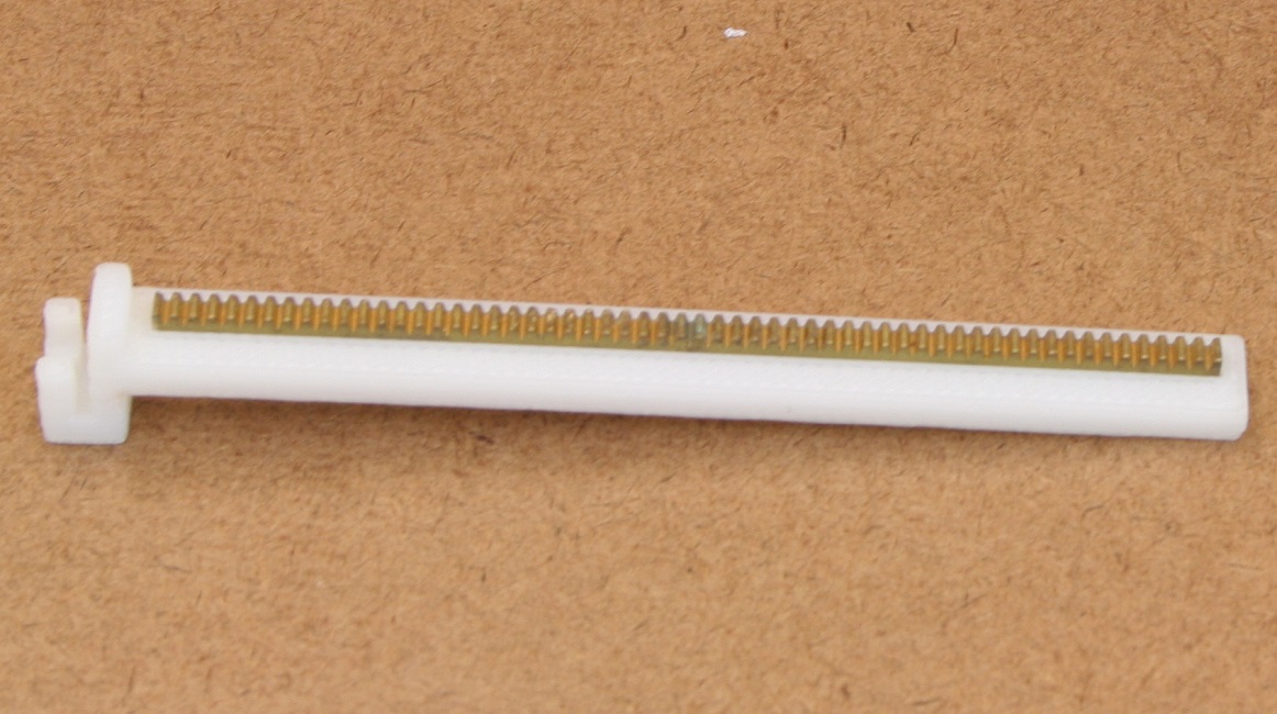
| Assemble the slide
Insert the cut to size rack into the grove in the plastic slide. If the rack is too long you may file it shorter. If the rack is too short a small amount of epoxy will fix it into place.
Tip: If your having trouble pressing the rack into it's grove you may gently press it in with a bench vice. Do not over tighten or you may damage the plastic parts.
|
|---|
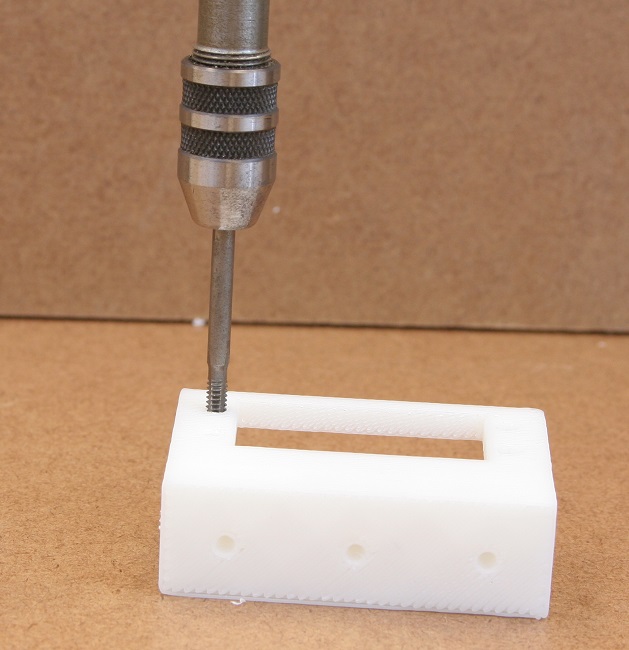
| Tap all holes
Using a 6-32 (or appropriate metric) tap, tap all holes in the 3d printed parts. There should be a total of 11 holes in the current version.
|
|---|
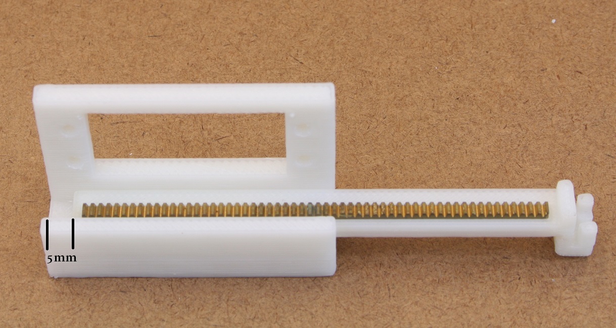
| Place slide in body
Fit the slide in the pump body with the back approximately 5mm from the edge of the body. If there is too much friction you may file the sides of the slide down slightly. Some friction is okay as the parts will wear in after a few hours of use.
|
|---|
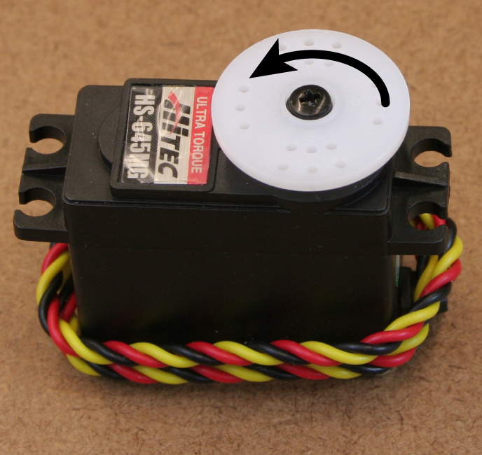 
| Prep the servomotor
- Rotate the servo motor to full lock counter clockwise (it should turn no more than 180degrees so don't force it).
- Unscrew and remove the servo horn (white disc). The horn may be discarded but keep the screw.
- Clip the vertical tabs on either side of the servo motor. These prevent the motor from being mounted flat in a later step.
|
|---|
| Mount the servomotor into the pump body
Insert the servomotor into the pump body and attach it with four 1/4" machine screws.
NOTE: With the newest design it's easier to mouth the gear first (see next step).
|
|---|

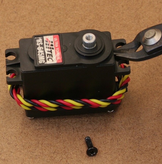
| Mount the gear to the servo drive shaft
|
|---|
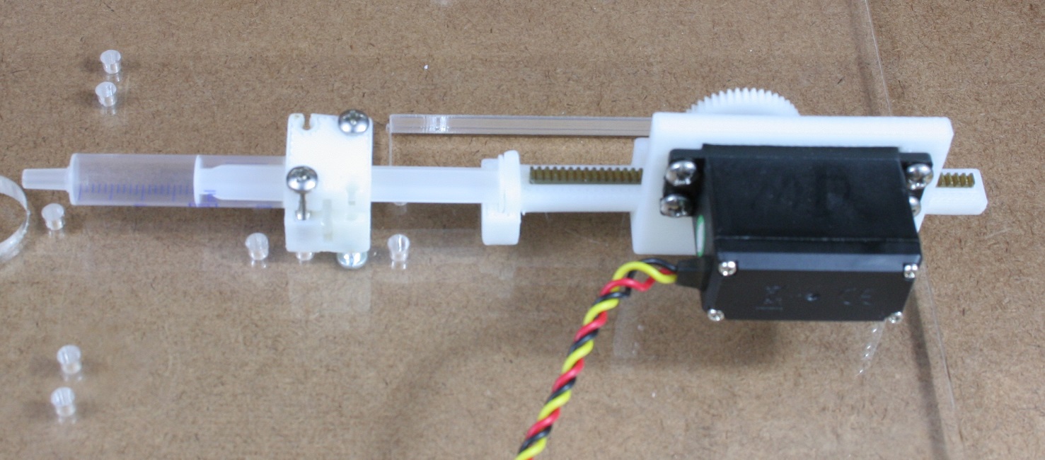
| Mount the pump assembly, syringe holder, and syringe
- Screw the pump body to the mount using at least two screws.
- Using two more screws attached diagonally attach the bottom (larger of the two) syringe holder to the mounting.
- When ready to run the pump insert the syringe as shown. Syringes are meant to be used one time and thrown out.
|
|---|


