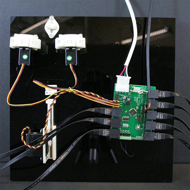
You will likely want to assemble all parts in an incubator. Below we show the where wires should go to connect the turbidostats, and pinch valves to the main controller board.
The "Main Board" then connects to your Mac/PC to output all data and accept commands.
Version 2.0
Version 2.0 attachment is nearly the same as version 1.0. Version 2.0 allows you to use all solenoid pinchvalves. If you choose to use solenoid pinchvalves then follow the hookup photo below. Otherwise hook up just the media pinchvalve to position 0.
Version 1.0
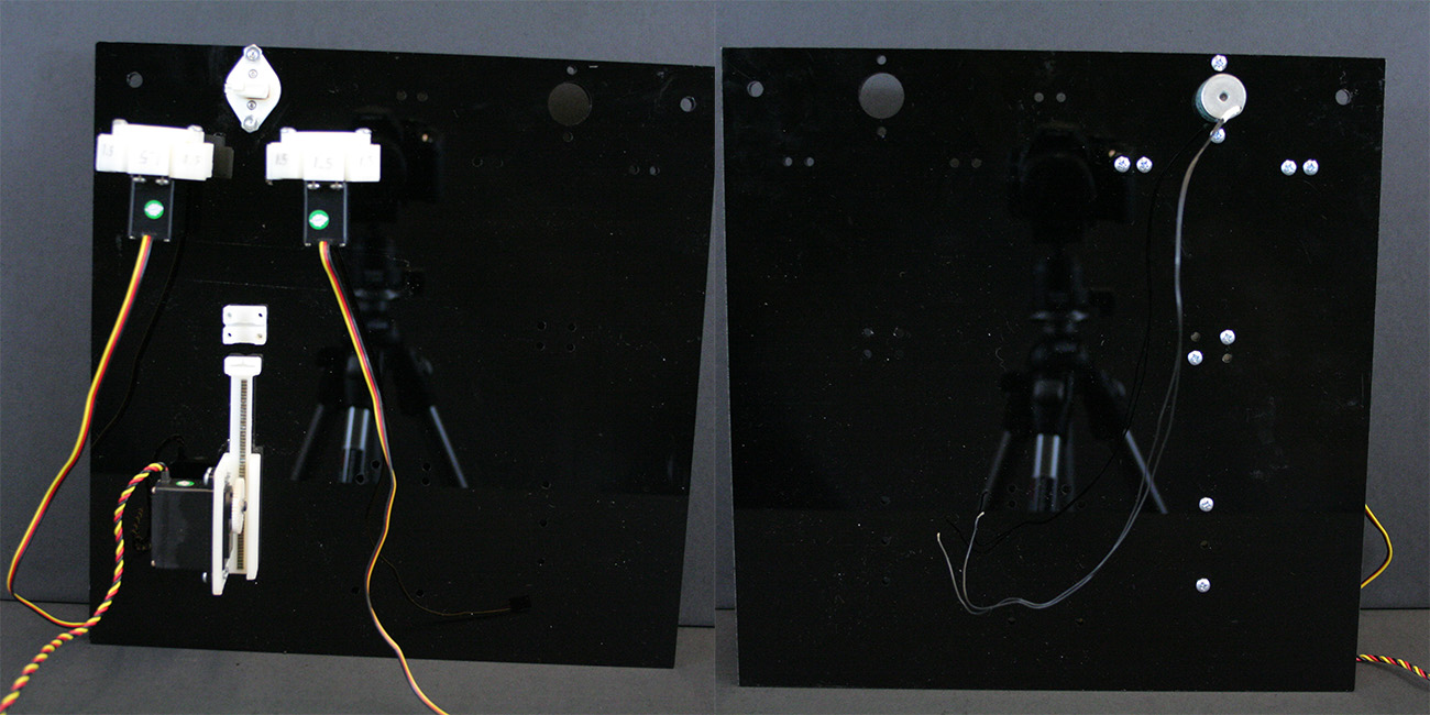
| Mount the pump and pinch valves:
- Mount the pinch valves to a flat surface. This surface may be either vertical as pictured or mounted flat near the top of your incubator.
- Mount the 3D pinted syringe pump onto a flat surface as shown in it's assembly page. This surface should then be mounted so that the port of the syringe faces up to facilitate purging of bubbles from the media lines.
Note: Ideally, once inserted the syringe should be mounted close to the pinchvalves.
Note: You may click any photo to enlarge.
|
|---|
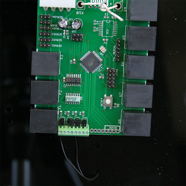
| Mount the main board
- The mainboard may be monted in any orientation that makes assembly convenient.
- Attach leads from the solenoid pinchvalve into the first and fifth screwterminal positions as pictured (click to enlarge). Note: for the v2.0 board the pinch valves plug into the header pins labeled "0".
Note: Make sure the mainboard is mounted to a non-conductive surface.
Note: The current board design lacks mounting holes so you make have to get creative (see photo).
|
|---|
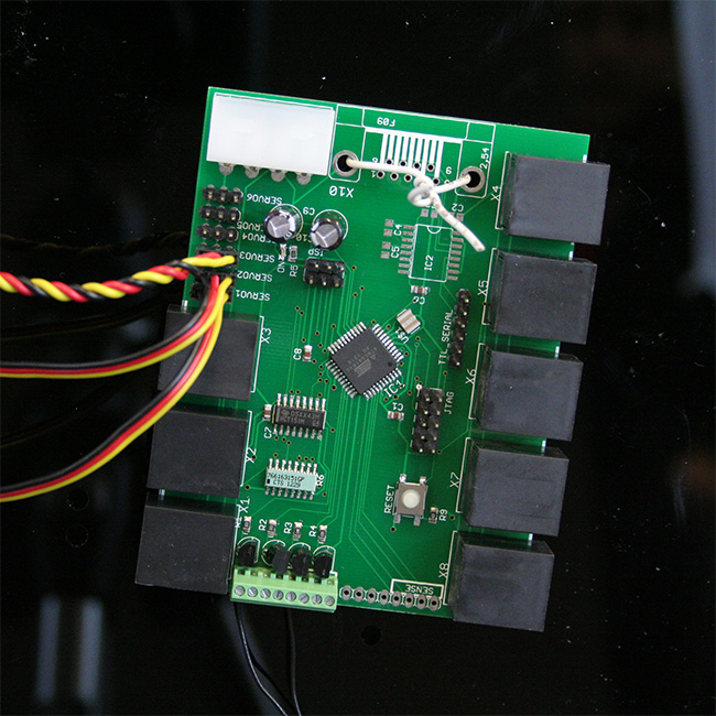
| Connect the servos
- Connect the 3D printed pinch valves to the servo headers. The headers marked "servo1" attach to pinchvalve 1-4 and the headers marked "servo2" attach to the pinchvalve 5-8.
- Connect the 3D printed syringe pump to the servo header marked "servo3"
WARNING: The servo connections are directional but not keyed! The black wire should always face out and the yellow wire should always face in (as pictured).
Note: servo4 is for an additional pump while servos 5 and 6 will control additional pinchvalves. This can be used for mixture control.
|
|---|
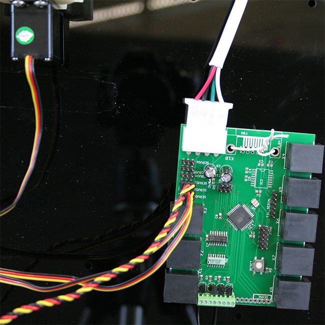
| Attach the power connector
- Attach the power connector as shown.
Note: The connector is keyed so if it hard to connect double check that the orientation is correct. Forcing the connector in backward will result in damage to the mainboard.
|
|---|
| Connect the serial port and chamber cables
- Connect the serial cable with the black wire toward the reset button (down in the photo).
- Connect all eight chamber cables and label the other ends 1 through 8 corresponding to the number written on the main board (X1, X2, ..., X8).
Note: Port X1 connects to chamber 1, X2 to chamber 2, etc.
Note: For lengths further than two feet we recommend using ethernet cables with 24 gauge wiring.
Note: Do not connect the turbidostat's RJ45 ports to any other devices!
|
|---|
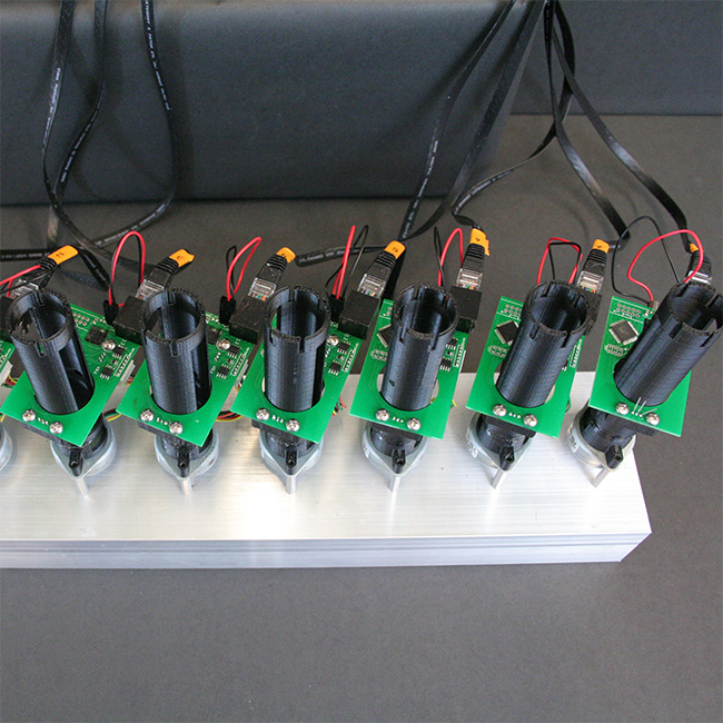
| Connect the chambers
- Connect the chamber cables in numerical order. The cable number determines the chamber number during setup.
|
|---|
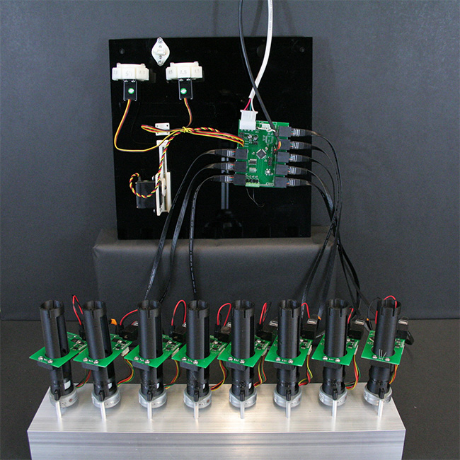
| Check connections
- Check all connections
- Check that the USB-serial cable is connected with the black wire toward the reset button
- Check that all servos are attached with the yellow wire inward.
- Check that all chambers are hooked up and you know how the chambers are indexed (Chamber number is determined by the RJ45 port it is plugged into.)
- You may now turn on (plug in) the power supply and continue to the [[Setup
Note: Your turbidostat is now ready for normal opreation. All assembly required for each experiment is covered in the operating manual.
|
|---|


