Movement of from the sterile media source, into the syringe (mounted in the syringe pump) and into the individual chambers is controlled by accurate and inexpensive 3D printed pinch valves. These valves allow media to travel through only one piece of media tubing at a time via a spinning CAM in the center of the 3D printed portion of the pinch valve. Commercial pinch valves can be used in place of our homemade version and instructions are listed [Here].
photo here
exploded diagram here
Design files
Alibre/Geomagic and STL files can be found on github or through the
direct link
3d Prited Parts
See the hardware-firmware\pinchvalve directory within github for STL files, which can be used with most 3d printers.
Laser Cut Parts
Some parts are laser cut now to make them more robust.
For laser cut parts use 5mm ± 0.1mm (about 0.19in) thick delrin. A vector file for laser cutting is available in the github repository link above in the location hardware-firmware\pinchvalve\P1-delrin laser parts-ponoko.eps
Actuator
HS-485HB BB standard servo (see parts spread sheet for one possible vendor) or better (eg metal gears)
Electronics
none.
Purchased Parts
none.
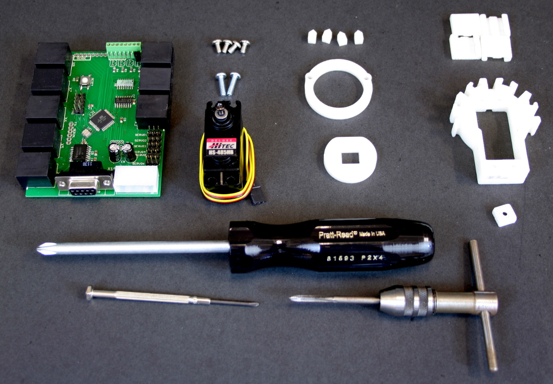
| Gather all 3d printed parts:
- end clip 4x
- Pinchvalve body
- Center adapter
Gather all Delrin parts:
- pinchers 4x
- front cover
- center cam
Gather all Hardware:
- 6-32 1/4" screws 4x
- 6-32 1/2" screws 2x
Tools:
- #2 screwdriver
- #0 screwdriver
- 6-32 tap
Other parts
|
|---|
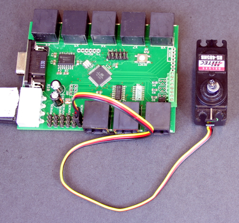
| Plug the servo into the mainboard. Plug the servo motor into the 'servo1' location in the mainboard and hit the reset button. This should center the servo.
Note: Make sure that the mainboad is powered and its firmware has been flashed.
Note: You may want to complete the next step while the servo is still plugged in. This will prevent it from getting knocked out of center.
|
|---|
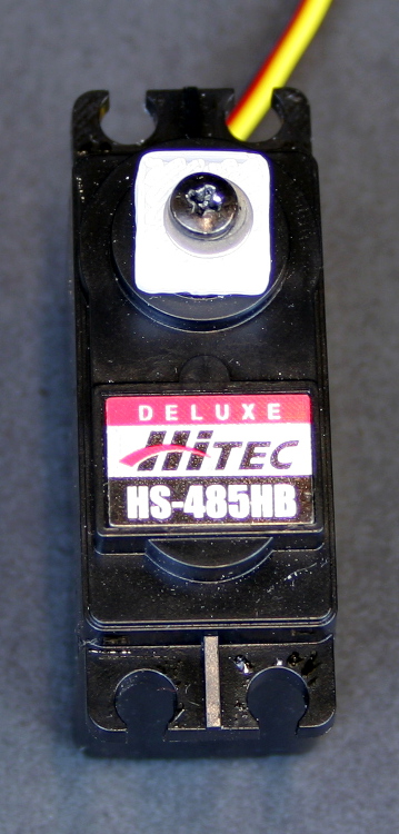
| Press fit the cam adapter over the servo motor's drive shaft. The harder plastic in the drive shaft should cut teeth into the softer ABS plastic giving a secure fit.
|
|---|
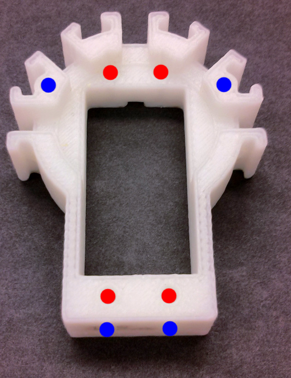
| Tap all holes with the 6-32 tap. Holes marked in blue should be tapped from the front (as seen by the camera) and holes marked in red should be tapped from behind.
|
|---|
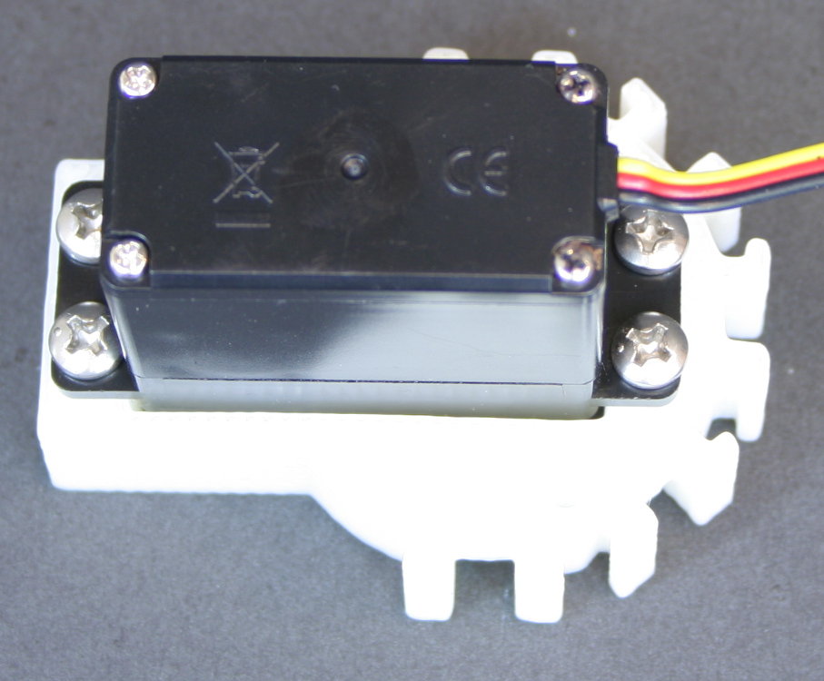
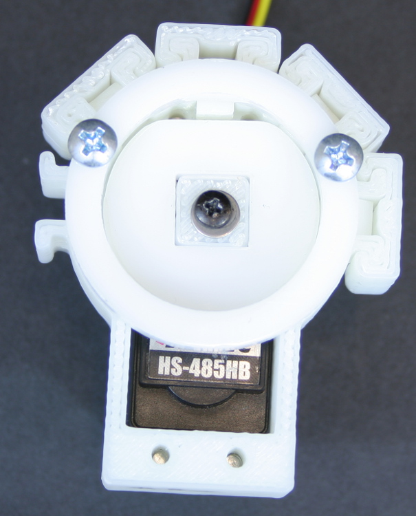
| Mount the servo to the pinch valve body. Turn the body face down. Using the four 1/4" screws, attach the servo motor to the pinchvalve body from the back side (as pictured from the previous step).
|
|---|
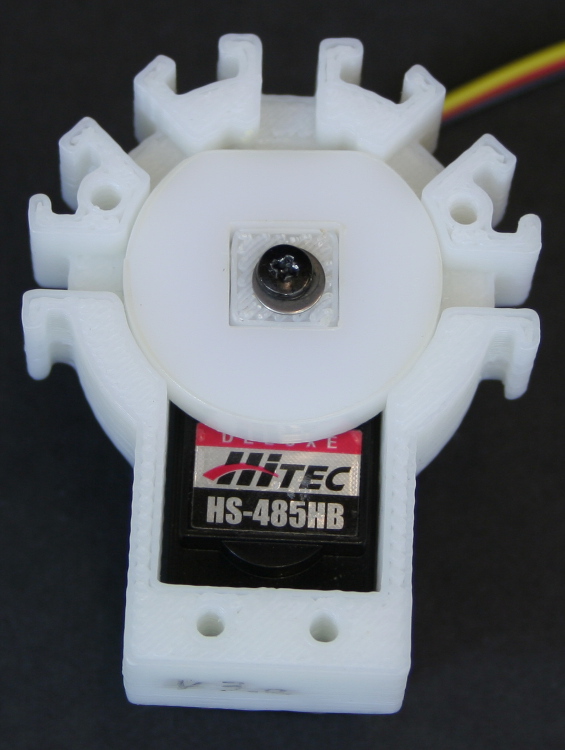
| Attach the cam to the servomotor. Turn the assembly back over and attach the cam so that the flat side is facing up.
|
|---|
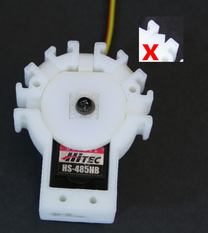
| Insert four pinchers. Insert the four delrin pinchers into the right most four openings, leaving the left most opening open. Make sure the pinching surface is oriented so that it spans the entire opening (see photo).
Note: from here until the last step, do not tip the assembly or the pinchers may fall out.
|
|---|
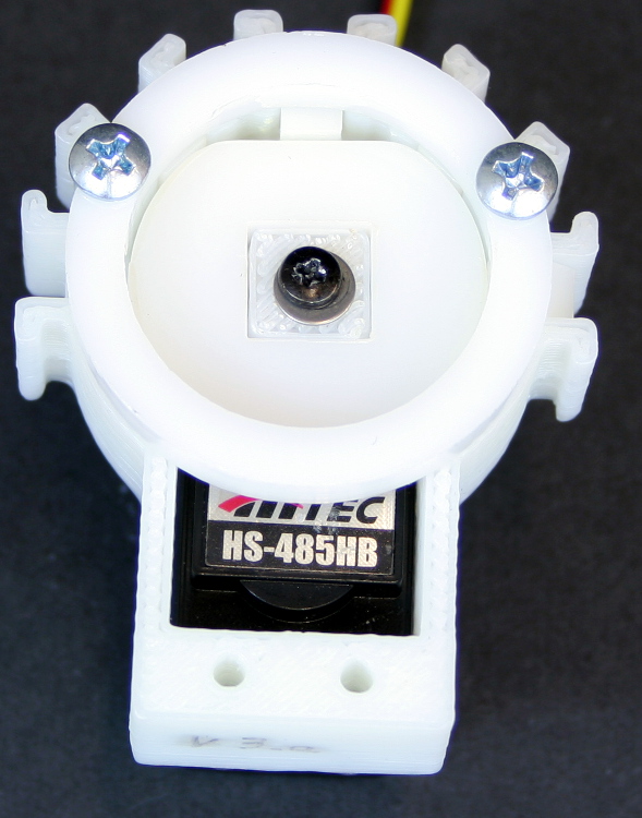
| Attach the front cover. Attach the delrin front cover using the two 1/2" screws.
|
|---|
| Attach the four retention clips.
|
|---|


