NOTE
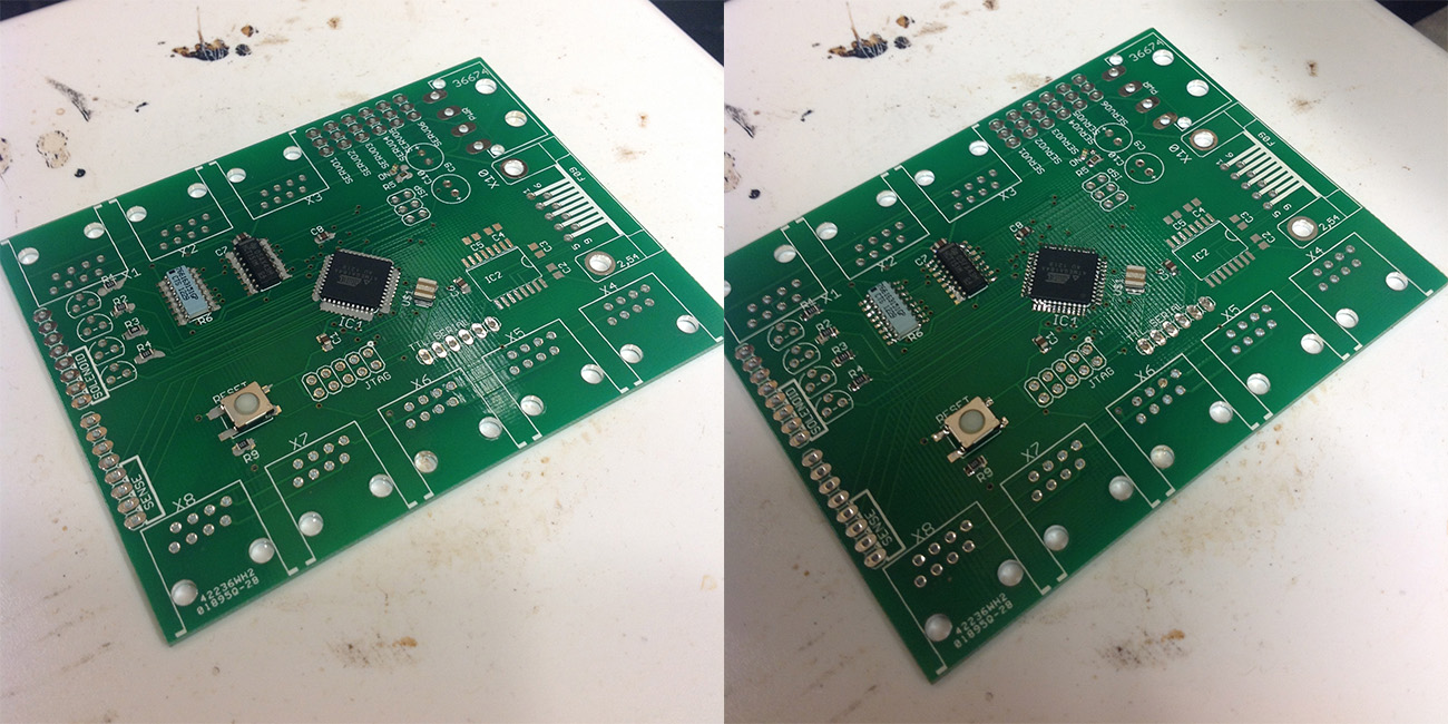
The component placement for the Flexostat V2.0 PCB has changed somewhat. See the photos below for surface mount and through hole part placement.
The "Main Circuit Board" or "Main Board" is principally responsible for taking in turbidity measurements taken many times a minute and using those to determine the dilution rate for each chamber on a minute by minute basis. Additionally it connects to your Mac/PC to output all data and accept commands. For each arrangement of 8 or fewer turbidostats you will need to make one "Main Board".
It should be noted that this main board connects to a 12V/x amp power source which can be dangerous. As such this part should be encased in a non-conductive material and particular care should be taken when working with and attaching wires to the leads. Further safety instructions are included in the Final Assembly section.

| Step 1. Gather all parts and tools:
Tools
- Main Circuit Board
- tweezers
- CHIPQUICK solder paste (or similar)
Surface Mount Parts
- ATMEGA164a (orientation matters)
- Ceramic oscilator (orientation matters)
- 74HCT151 (296-9254-5-ND) (orientation matters)
- 150ohm or 180ohm (recommended) resistor network (766-163-R150P-ND, 766-163-R180P-ND)
- 4x 1.0uF ceramic capacitors
- 1kohm resistor 0805
- 5x 10kohm resistors 0805
- button
- LED (orientation matters)
Through-hole Parts
- RJ45 connector (orientation matters, but it only goes in one way)
- Molex connector (orientation matters, but it only goes in one way)
- screw terminal (orientation matters)
- breakaway 0.1" header strip
- Large electrolytic capacitors (10-1000uF) (orientation matters (or it may explode))
- BS107 (orientation matters)
|
|---|
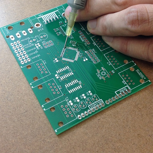 
| Step 2. Apply CHIPQUICK to the Main circuit board.
- To apply CHIPQUICK use the blunt needle adaptor to add a minimal quantity of solder.
- Apply CHIPQUICK to all areas where surface mount parts will be placed.
- Use tweezers to lay the ATMEGA164A onto the OD board and place it such that it so that each pin lays directly over its respective pad.
- Note how the dot on the part matches the dot silk screened onto the circuit board.
|
|---|
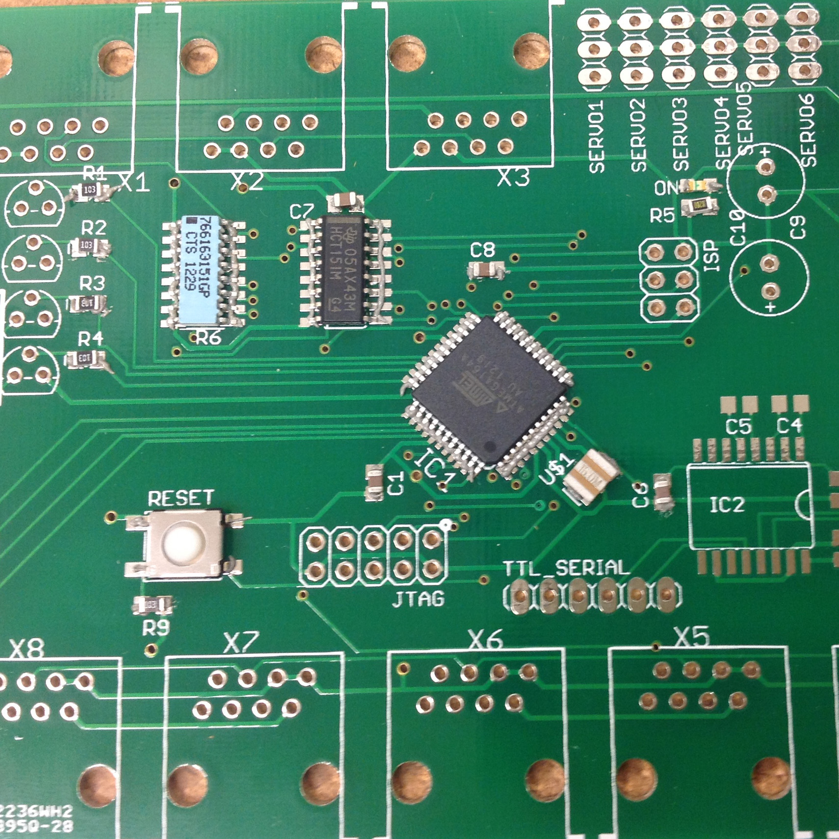
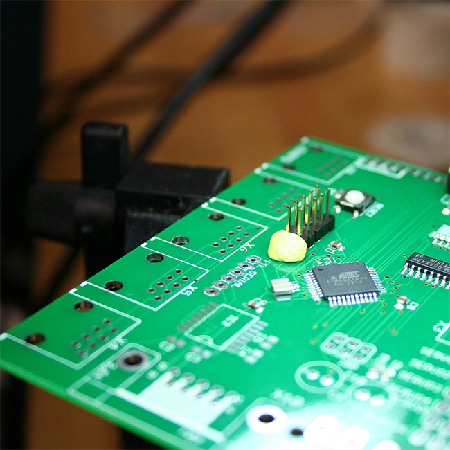
| Step 3. Apply all surface mount parts in the correct orientation.
- Next add the remainder of the surface mount parts with special attention to orientation of each of the parts. (zooming in on the image may help).
|
|---|
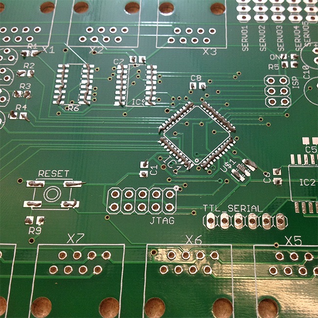
| Step 4. Solder all surface mount parts at 230C.
- Once all of the parts are on there and in the correct orientation they may be soldered into place at 230C using a standard laboratory hot plate. This work should be performed in a fume hood as gases will emanate off the board as the solder heats up and flux burns off.
- As the board heats the CHIPQUICK solder will go from having a dull grey appearance to shiny and metallic and small wisps of smoke may be visible.
- Once the solder on all parts become shiny and metallic simply use tweezers to slide the curcuit board onto a pot holder or other heat-tolerating substance. Be careful not to disturb the parts on the board as they will require a few seconds to cool.
- Note that once the solder cools it may have a dull finish if lead free solder is used. This is okay. Leaded solder should maintain a shinier finish.
|
|---|
| Step 5. Place and solder the BS107.
- Readjust the leads on each BS107 so that they fit int the main circuit board. The orientation is indicated by the PCB silkscreening.
- Solder each of the BS107 in place.
- Trim the leads off each BS107.
|
|---|
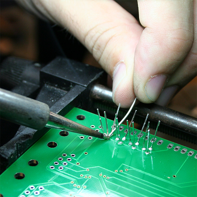
| Step 6. Cut the headers to size and solder to holes closest to the ATMEGA164a.
- Cut or break the headers to the appropriate length.
- Using poster tack or tape to hold headers in place and solder it on the surface mount part side of the main board.
- Solder the headers into the set of 2x5 holes closest to the ATMEGA164a.
|
|---|
 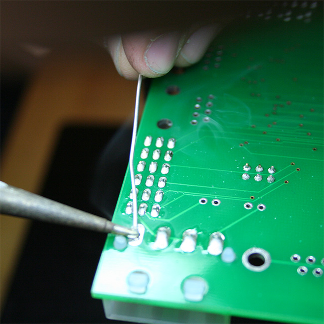
| Step 7. Solder on Molex connector and place the rest of headers into all other through-hole locations.
- As before use poster tack or tape to hold through hole parts into place before soldering.
- The molex connector clips into place and can be soldered without poster tack or tape.
|
|---|

| Step 8. Solder on the RJ45 connectors.
- clip on the RJ45 connectors and solder them.
|
|---|
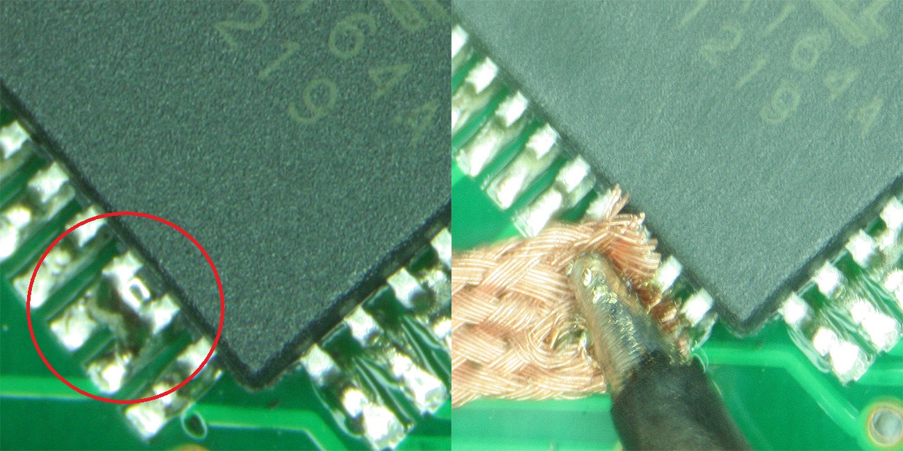
| Troubleshooting Soldering.
- One common problem, especially when soldering the surface mount parts is that multiple pins may be connected by excess solder.
- To remove excess solder place this region under a piece of copper braid (aka "solder wick") and apply heat until the excess solder has been removed by capillary forces.
|
|---|


