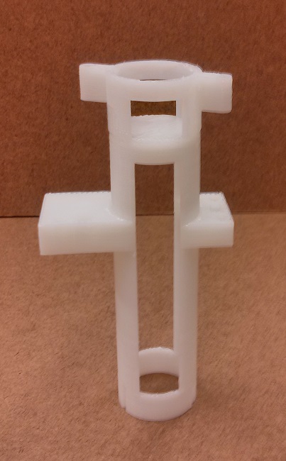
Each culture tube is held by a 3D printed culture tube holder. These culture tube holders can be mounted to an aluminum stand to organize your array of tubes - and also hold the red wavelength laser and 'OD board'.
3d Prited Parts
Alibre/Geomagic and STL files can be found on github or through the
direct link
see the "chamber" directory.
Laser Cut Parts
None
Actuator
FP35T-48L4
Electronics
OD Board
Purchased Parts
- stepper motor (for stir bar)
- magents (for stir bar)
Assembly
For a complete setup repeat these instructions 8 times (steps may be done in parallel).
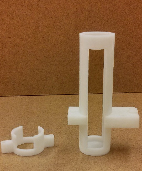 
| Gather all 3d printed parts:
- Chamber (left)
- Motor mount (left)
- Stir magnet holder (right)
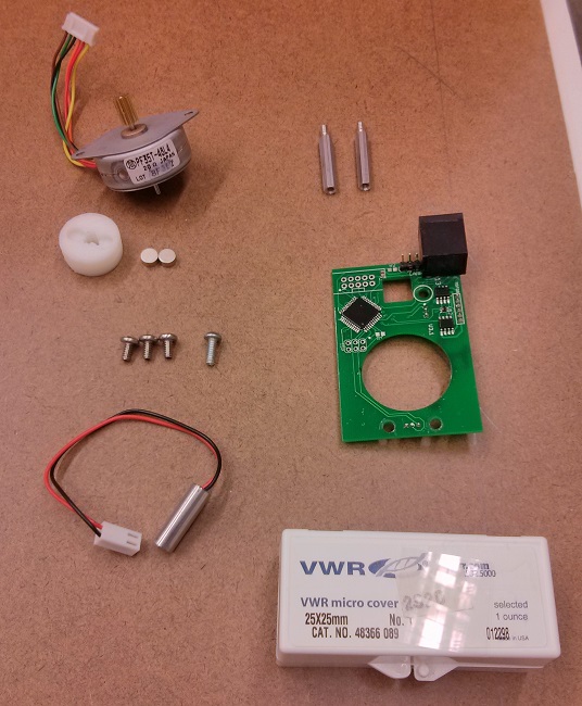
Gather all chamber electronics and hardware (right photo):
- Stir motor
- Stir Magnets
- 1" aluminum standoffs (narrow)
- 3x 6-32x1/4" machine screws (M3.5 (better) or M3 (ok) will work if you're outside of the US)
- 1x 6-32x3/8" machine screw
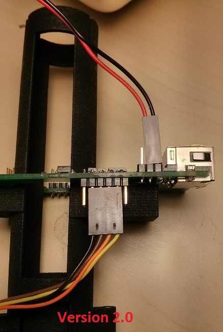
- Assembled chamber circuit board
- 650nm 7mm dia Laser
- Microscope slide coverslip (12mmx12mm (preferable) or 25x25mm (ok))
Note: If you do not have a 3d printer there are services that will do the printing for you. Alternatively, I'd be happy to print parts at cost or in exchange for raw plastic.
|
|---|
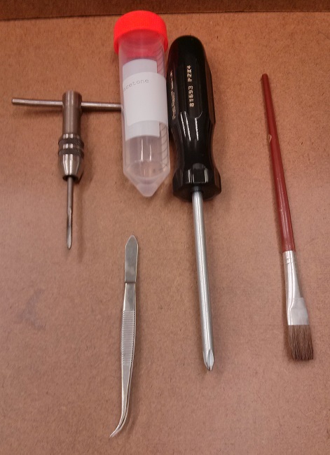
| Gather all tools needed for assembly:
- 6-32 tap (or appropriate metric tap if you're using metric screws)
- Tweezers
- Acetone (or epoxy)
- #2 screwdriver
- small paintbrush
|
|---|
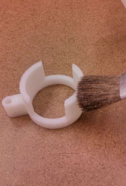 
| Glue the chamber body to the motor mount.
Using the acetone and paint brush to apply enough acetone to the mating surfaces of the motor mount and chamber to soften the ABS plastic (left). Then quickly press the two parts together making sure to align the windows. If the acetone is evaporating too quickly you may add additional acetone near joint after assembled, which will wick into the joint.
Note: Depending on the 3D printer and material acetone may not melt the plastic. In this case, you should use two part 5-minute epoxy to glue the parts together.
|
|---|
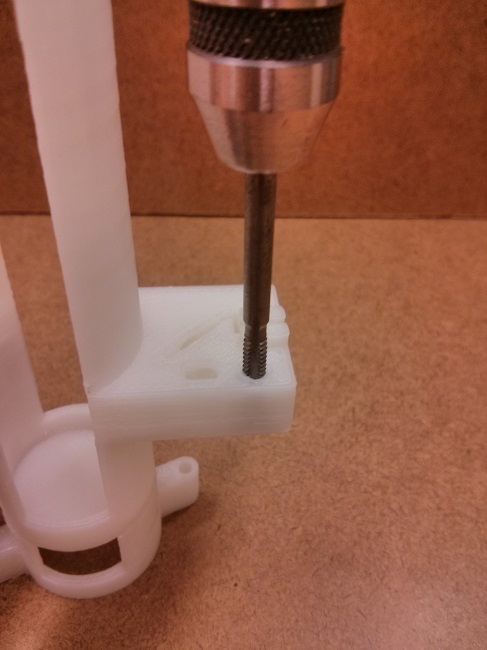
| Tap all screw holes
There should be six screw holes at the time of this writing (version 7.0), two for the motor, three for the PCB, and one for the laser.
Note: Be sure not to tap threads too deep into blind holes as it could cause damage to the part.
|
|---|
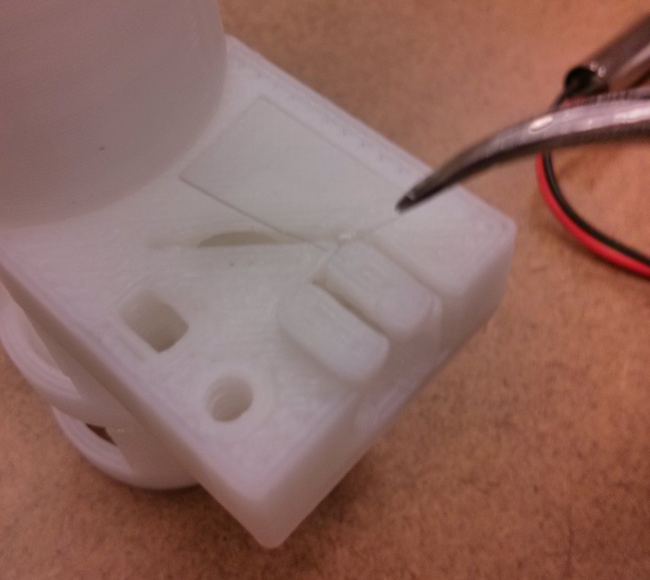
| Insert cover slip into slot in chamber
They do not make cover slips small enough to fit will into the turbidostat chamber. As a result you must cut them down to size. In a pinch, cover slips can be carefully broken down to size but its much better to use a glass cutter or glass cutting tile. The cover slip must be roughly 10-12mm wide and 4-6mm tall.
Note: If the cover slip is loose after insertion it is recommended that you apply a small dab of 5-minute epoxy to either side.
Note: Care must be taken not to allow the cover slip to protrude out of its slot or it will be shattered during the next assembly step.
Note: Do not skip this step (or any others really). The cover slip is necessary for the operation of the OD measurement electronics.
|
|---|
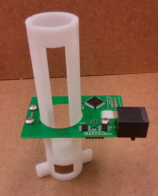
| Screw the OD board into the chamber body
Insert the OD board over the chamber body light sensors down making sure the light sensors fit snugly into the two rectangular holes. Secure the OD board using the three 6-32x1/4 machine screws.
Note: Do not over tighten the screws or you may damage the chamber body. A quarter turn past touching is all that's needed.
|
|---|
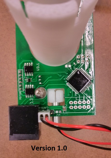 
| Attach laser to chamber body
Insert the laser into the 7mm opening on the front of the chamber body. The laser should easily slide 6-7mm into the body. With the laser inserted screw the 6-32x3/8 machine screw into the hole to the right of the laser until it just touches the side of the laser receptacle (right photo). Gently tighten until the laser is snug. Finally, plug the laser's wires into the left most two header pins leaving the pin closest to center empty. Make sure that the red wire is hooked up to the center pin.
Note: Over tightening the laser may cause misalignment.
|
|---|
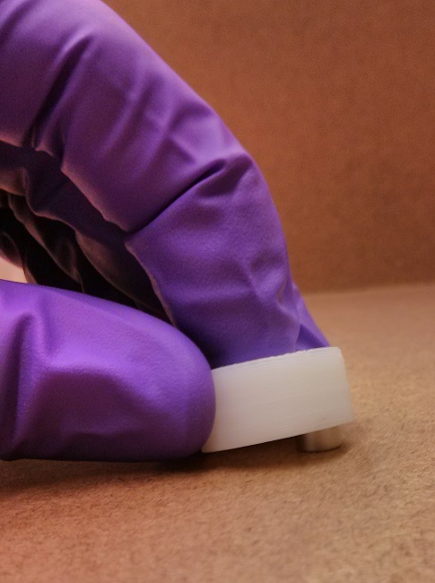 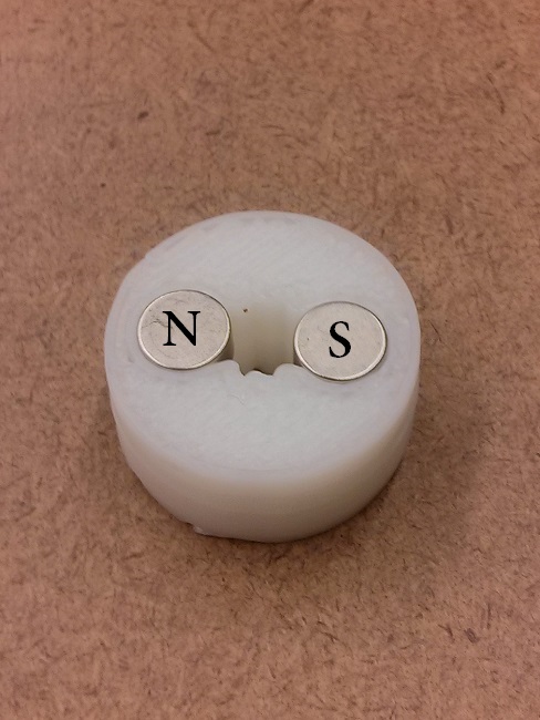
| Insert magnets into stir magnet holder
Place a single magnet on your bench and press fit (hard) until the magnet is flush with the surface of the holder. Repeat with the second magnet making sure it has been inserted with the opposite polarity.
|
|---|
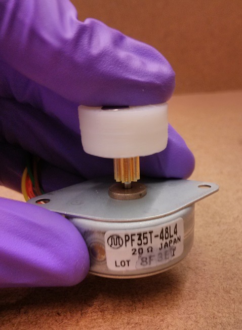 
| Insert motor into stir magnet holder
Line up the gear teeth with the cutout in the bottom side of the motor mount. Press the magnet holder firmly onto the motor gear until the gear touches the bottom side of the magnets. Be sure to apply forces along the axis of motor shaft and only apply force to the magnet holder, gear, and motor shaft.
Note: Do not apply force to the motor body. Doing so may damage the motor.
|
|---|
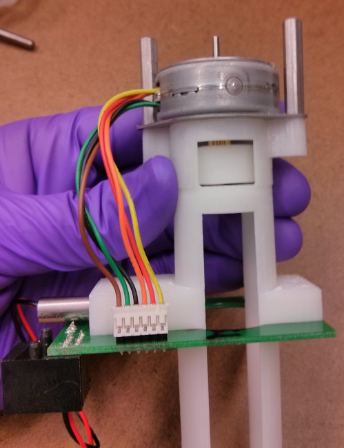
| Attach the motor to the chamber body
Using the two 1" standoffs, screw the motor to the chamber. Make sure the wires exit the laser side of the motor. Next attach the 6pin motor header onto the OD board.
Note: The 6pin header is not polarized and orientation does not matter. Changing the connector orientation only effects the direction the stir bar spins.
Note: It is easy to get this connector offset by one position. If the stir motor does not spin check this first.
|
|---|
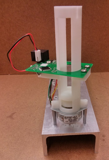 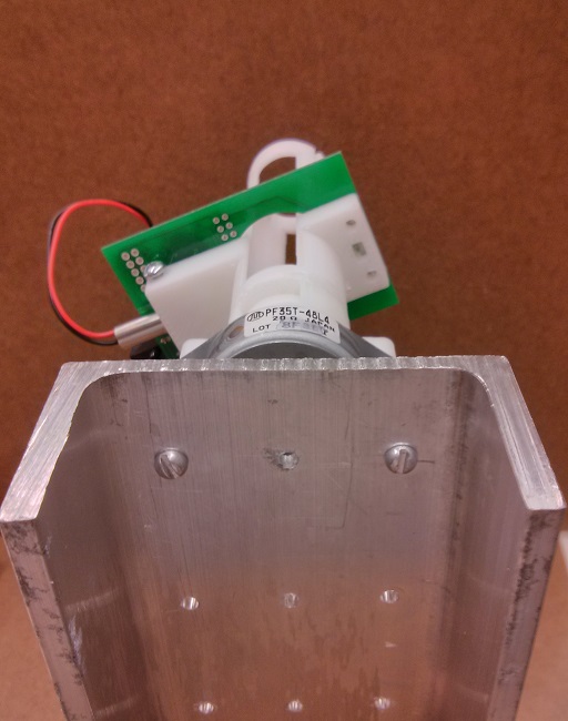
| Mount the chamber
Using the two standoffs as attachment points mount the chamber onto whatever you're using as a base.
I recommend using a piece of 3"-4" wide 18" long u-channel aluminum. Aluminum is easy to cut and machine and can be drilled with standard drill bits and a hand drill. Choosing u-channel will allow for the screw heads to protrude and keep the chambers up off the surface they are set on, which can help protect them from spilled media. I also recommend using aluminum standoffs and aluminum screws (only for mounting) to prevent galvanic corrosion. The rest of the screws should still be stainless steel if possible.
|
|---|


